High-speed cross slot milling machine

A slot milling machine and cross technology, which is applied in the field of high-speed cross slot milling machines, can solve the problems of slow cutting speed of the workpiece and inability to cut cross-shaped slots on the surface of the workpiece.

Pending Publication Date: 2021-12-28
宁波市北仑区丛峰机械有限公司
View PDF1 Cites 1 Cited by
  • Summary
  • Abstract
  • Description
  • Claims
  • Application Information

AI Technical Summary

Problems solved by technology

[0005] The object of the present invention is to provide a high-speed cross-shaped slot milling machine to achieve cross-shaped slot milling in order to overcome the problem that the cutting speed of the workpiece in the prior art is relatively slow and the cross-shaped notch cannot be cut on the surface of the workpiece. The machine has the function of quickly cutting the cross-shaped notch on the workpiece in one feed

Method used


Image

  • High-speed cross slot milling machine
  • High-speed cross slot milling machine
  • High-speed cross slot milling machine

Examples


specific Embodiment 1

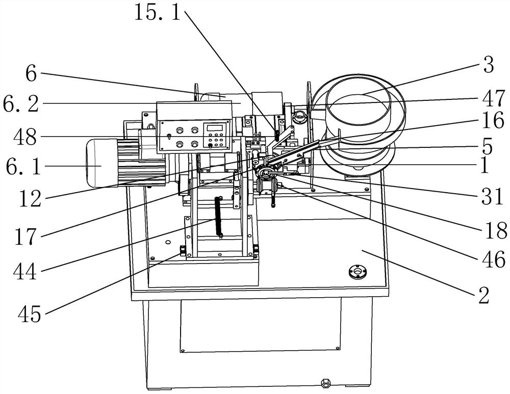
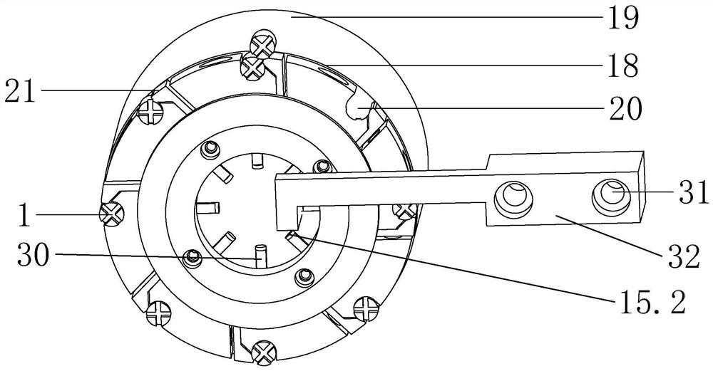
[0036] like figure 1 or figure 2As shown, a high-speed cross milling machine includes a frame 2, a feed structure 16 arranged above the frame 2, a clamping structure 18 arranged below the feed structure 16 and fixed on the frame 2, Milling cutter structure 46, discharge structure 31 close to the surface of clamping structure 18, linkage structure 47, reset structure 48; The seat 19 is provided with eight symmetrically distributed workpiece grooves 20, and beside the workpiece grooves 20 on the clamping disc seat 19, an elastic pressure sheet 21 for clamping the workpiece 1 is also provided. The feeding structure 16 includes a feeding guide rail 5 and It is used to push the workpiece 1 into the feed link 12 of the clamping structure 18. The lowermost end point of the feed link 12 is against the lowest point of the feed guide rail 5, and the contact between the feed link 12 and the feed guide rail 5 A clamping bracket 17 is provided, and the clamping bracket 17 is closely att...

specific Embodiment 2

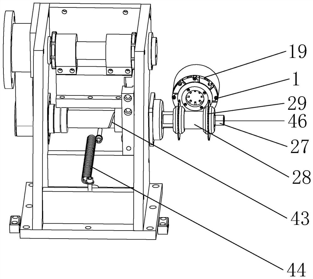
[0039] like image 3 or Figure 4 As shown, on the basis of Embodiment 1, the milling cutter structure 46 includes a milling cutter spindle 27 and a milling cutter 29, the milling cutter spindle 27 and the milling cutter 29 are connected by a milling cutter spacer 28, and a pair of milling cutter spindles are arranged on the same milling cutter spindle 27. The milling cutter 29 that is arranged horizontally, the distance between two milling cutters 29 is equal to the distance at the axis of the two workpieces 1 separated by 90 degrees on the clamping disc seat 19, and the milling cutter spindle 27 is provided with a lubricant for milling cutter spindle 27. The helical lubricating groove 43 is provided with oil seals at both ends of the lubricating groove 43 respectively. A high-speed cross milling machine also includes a driving structure 6. The driving structure 6 includes a motor 6.2 and a reduction motor 6.1. The motor 6.2 is used to drive the milling machine. The cutter s...

specific Embodiment 3

[0042] like Figure 5 As shown, on the basis of Embodiment 2, the discharge cam 10 is adapted to the needle roller bearing 33, the upper end of the needle roller bearing 33 is connected to the discharge structure 31, and the semicircle outside the discharge cam 10 is provided with a raised structure 34. The edge of the raised structure 34 gradually becomes higher in the middle, the distance between the needle roller bearing 33 and the discharge cam 10 is smaller than the highest point of the raised structure 34, and the discharged structure 31 includes a right-angled discharge plate 35 and a discharge ejector pin 32, The outside of the right-angle discharge plate 35 is connected to the discharge ejector pin 32, and the inboard of the right-angle discharge plate 35 is connected to the chute 36. The frame 2 is provided with a turbine box 38, and the turbine box 38 is fixedly connected with a screw for matching with the chute 36. The protruding bar 37, the chute 36 is slidably co...


PUM


Abstract

The invention discloses a high-speed cross slot milling machine. The high-speed cross slot milling machine comprises a rack used for fixing and supporting the slot milling machine, a feeding structure used for straightening workpieces to be machined and feeding the workpieces, a clamping structure used for clamping and fixing the workpieces to be machined, a milling cutter structure used for cutting the surfaces of the workpieces located on the same horizontal line at the same time, and a discharging structure used for ejecting out the machined workpieces. The high-speed cross slot milling machine further comprises a linkage structure used for synchronizing the working process of the feeding structure, the working process of the discharging structure and the working process of the clamping structure, and a reset structure used for resetting the milling cutter structure and the discharging structure. According to the high-speed cross slot milling machine provided by the invention, the cross slot milling machine has the function of rapidly cutting cross-shaped slots in the workpieces through one-time feeding.

Description

technical field [0001] The invention relates to the technical field of slot milling machines, in particular to a high-speed cross slot milling machine. Background technique [0002] The slot milling machine is mainly used for the subsequent secondary processing of automatic lathes. It can be modified to realize milling flat slots and other processes, and it can also be equipped with drilling, tapping, chamfering and other processes. It is also called a compound machine, a special machine tool. It can also be used for milling grooves of various metal materials, plastic materials and other non-standard metal materials. [0003] At present, the cutting speed of the workpiece of the milling machine is relatively slow, and the cross-shaped notch cannot be cut on the surface of the workpiece. Some cross-shaped slot milling machines need to enter the knife twice for cutting when cutting the cross-shaped notch on the surface of the workpiece. [0004] For example, a kind of "a kind...

Claims


Application Information

Patent Timeline
Patent Type & Authority Applications(China)
IPC IPC(8): B23C3/30B23C9/00
CPCB23C3/30B23C9/00
Inventor 甘祥飞
Owner 宁波市北仑区丛峰机械有限公司
Why Eureka
Try Eureka