Positioning and punching device for building steel formwork production and machining and punching method

A drilling device and construction steel technology, applied in the direction of manufacturing tools, other manufacturing equipment/tools, etc., can solve the problems of high temperature in the opening area of ​​the steel formwork, poor natural cooling efficiency, and inconvenient drilling, etc., to achieve extended drilling Hole working time, accelerated air flow, and the effect of improving production efficiency

Inactive Publication Date: 2021-12-28
溆浦县贺老九钢结构有限公司
View PDF1 Cites 1 Cited by
  • Summary
  • Abstract
  • Description
  • Claims
  • Application Information

AI Technical Summary

Problems solved by technology

[0005] The purpose of the present invention is to provide a positioning punching device and a punching method for the production and processing of building steel formwork, to solve the problem that the convex edge formed at the edge of the hole after drilling needs to be polished separately in the above background technology, and the punching is not convenient enough , the temperature in the opening area of ​​the steel formwork is extremely high, and the natural cooling efficiency is poor

Method used


Image

  • Positioning and punching device for building steel formwork production and machining and punching method
  • Positioning and punching device for building steel formwork production and machining and punching method
  • Positioning and punching device for building steel formwork production and machining and punching method

Examples


Embodiment Construction

[0033] The following will clearly and completely describe the technical solutions in the embodiments of the present invention with reference to the accompanying drawings in the embodiments of the present invention. Obviously, the described embodiments are only some, not all, embodiments of the present invention. Based on the embodiments of the present invention, all other embodiments obtained by persons of ordinary skill in the art without creative efforts fall within the protection scope of the present invention.

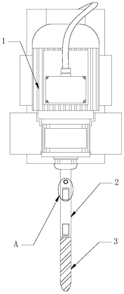
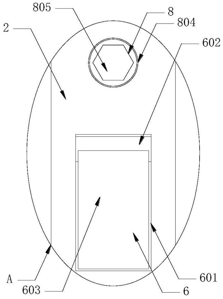
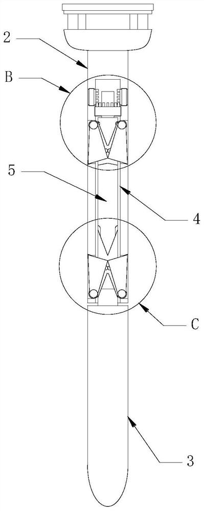
[0034] see Figure 1 to Figure 6 , the present invention provides a technical solution: a positioning and drilling device for the production and processing of building steel formwork, including an electric control drilling machine 1, the rotating end of the electric control drilling machine 1 is fixedly equipped with a link 2, and the link 2 The bottom end of the connecting rod 2 is provided with a drill bit 3, and the bottom of the connecting rod 2 is provided wit...


PUM


Abstract

The invention relates to the technical field of building steel formwork production, in particular to a positioning and punching device for building steel formwork production and machining and a punching method. The positioning and punching device comprises an electric control drilling machine, a connecting rod is fixedly installed at the rotating end of the electric control drilling machine, and a drill bit is arranged at the bottom end of the connecting rod. According to the positioning and punching device for building steel formwork production and machining and the punching method, an upper grinding device and a lower grinding device are arranged to be matched, an upper scraping block and a lower scraping block can be cut out and then driven by the electric control drilling machine, the upper scraping block and the lower scraping block make contact with the hole edges on the upper side and the lower side of a punched hole, so that convex edges generated by punching at the hole edges are scraped away, the operation is easy and rapid, grinding equipment does not need to be independently used for re-machining, the production efficiency is improved, in the process of grinding the convex edges of the punched hole, the upper scraping block and the lower scraping block which rotate at a high speed are used for disturbing airflow, so that air flow in the hole punching area is accelerated, cooling of the hole punching area of the steel formwork is accelerated, and the safety is better.

Description

technical field [0001] The invention relates to the technical field of building steel formwork production, in particular to a positioning and punching device and a punching method for the production and processing of building steel formwork. Background technique [0002] With the rapid development of our country, the construction industry is also developing rapidly. In the construction industry, in order to facilitate the construction of construction personnel or to assist in fixing the corresponding building structures, the corresponding steel formwork will be applied to the corresponding steel formwork. During the processing, the corresponding steel materials need to be cast, cut and drilled, and then fixed and installed by welding or bolting. [0003] The existing patent (publication number: CN212976815U) discloses a positioning and punching device for the production and processing of building steel formwork, including a fixed base and a positioning mechanism. Several sup...

Claims


Application Information

Patent Timeline
Patent Type & Authority Applications(China)
IPC IPC(8): B23P23/04
CPCB23P23/04
Inventor 贺元
Owner 溆浦县贺老九钢结构有限公司
Why Eureka
Try Eureka