Mechanical stirring, blowing and desulfurizing stirrer for metallurgy

A technology of mechanical stirring and agitator, which is applied in the field of iron and steel smelting technology, can solve the problems of mutual collision and growth, reduce the degree of bubble dispersion and miniaturization, low contact area and reaction time of gas-liquid desulfurization reaction, and achieve easy stirring of steel Liquid, reduce bubble aggregation, prolong the effect of gas-liquid reaction time

Active Publication Date: 2021-12-28
PANGANG GRP XICHANG STEEL & VANADIUM CO LTD +1
View PDF7 Cites 2 Cited by
  • Summary
  • Abstract
  • Description
  • Claims
  • Application Information

AI Technical Summary

Problems solved by technology

At present, this stirring and blowing method is to place the air blowing hole under the stirring paddle, and the bubbles are broken and thrown out by the stirring paddle during the floating process. The paddle and the rotary injection composite molten iron desulfurization agitator disclosed in the application number 201821570143.6 adopt this method, but through the physical water simulation experiment of mechanical agitation and injection by Liu Yan et al. No matter vertical hole injection, L-shaped horizontal injection or four-hole horizontal injection, the bubbles will quickly gather in the central vortex, reducing the degree of dispersion and miniaturization of the bubbles, which shows that the desulfurizer blown out by this stirring injection method is After the bubbles are blown out from the bottom, they will be attracted to the central vortex formed by stirring, so that a large number of bubbles cannot be crushed and thrown out, but collide with each other and grow up, accelerating to rise away from the molten pool, making the contact area and reaction time of the gas-liquid desulfurization reaction are at a lower level

Method used


Image

  • Mechanical stirring, blowing and desulfurizing stirrer for metallurgy
  • Mechanical stirring, blowing and desulfurizing stirrer for metallurgy

Examples


Embodiment Construction

[0022] The technical solutions in the embodiments of the present invention are clearly and completely described below in conjunction with the embodiments of the present invention. Apparently, the described embodiments are only some of the embodiments of the present invention, but not all of them. Based on the embodiments of the present invention, all other embodiments obtained by persons of ordinary skill in the art without making creative efforts belong to the protection scope of the present invention.

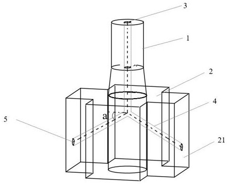
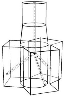
[0023] refer to figure 1 , the novel stirring jet desulfurization agitator provided by the example of the present invention comprises a stirring shaft 1 and a stirring head 2, the stirring shaft 1 is usually arranged vertically, and the stirring head 2 is connected under the stirring shaft 1 to form a fastening structure; the stirring head The outer side of 2 is provided with a plurality of stirring blades 21 along the circumferential direction, and the stirring blades 21 pr...


PUM


Abstract

The invention relates to a mechanical stirring, blowing and desulfurizing stirrer for metallurgy. The mechanical stirring, blowing and desulfurizing stirrer comprises a stirring shaft and a stirring head connected to the lower portion of the stirring shaft, wherein a plurality of stirring blades are arranged on the outer side of the stirring head in the circumferential direction, and the included angles between the adjacent stirring blades are the same; a straight-through air blowing channel is formed in the stirring shaft, obliquely downward flow dividing pipelines are arranged in part of or all the stirring blades, and each flow dividing pipeline communicates with the straight-through air blowing channel to form an air blowing channel; and a blowing opening is formed at the tail of each flow dividing pipeline. Desulfurizing agent blowing holes are formed in the outermost edge wall surfaces of the symmetrical stirring blades, and a certain distance is formed between a bubble generation position and a central vortex region, so that the bubble aggregation of a desulfurizing agent can be reduced, the bubble growth probability can be reduced, the gas-liquid reaction area can be increased, the gas-liquid reaction time can be prolonged, and the desulfurization reaction efficiency can be improved.

Description

technical field [0001] The invention relates to the technical field of iron and steel smelting technology, in particular to a metallurgical mechanical agitation blowing desulfurization agitator, in particular to a stirring paddle for magnesium-based stirring composite blowing molten iron desulfurization. Background technique [0002] Sulfur is detrimental to the quality of steel in most cases and will cause the problem of "hot embrittlement". Therefore, desulfurization process must be carried out. Since desulfurization of molten iron has the thermodynamic advantages of desulfurization, the desulfurization task of steel production is in the modern steel production process. Mostly located in the molten iron pretreatment link. Hot metal pretreatment desulfurization is mainly divided into KR method and injection method. Among them, the KR method uses stirring to form a vortex to substitute the desulfurizer into the molten iron for reaction, but there are problems of large iron l...

Claims


Application Information

Patent Timeline
Patent Type & Authority Applications(China)
IPC IPC(8): C21C1/02C21C7/064F27D27/00
CPCC21C1/02C21C7/064F27D27/00
Inventor 周遵传唐萍何鹏张彦恒梁新腾和秀山付灈文光华
Owner PANGANG GRP XICHANG STEEL & VANADIUM CO LTD
Why Eureka
Try Eureka