

Hydraulic walking device and control method thereof
A traveling device and hydraulic technology, applied in the direction of fluid pressure actuating devices, servo motors, servo motor components, etc., can solve the problems of limited transportation distance of large hydraulic cylinders, complex manufacturing process of large hydraulic cylinders, and high use costs, and achieve weight reduction. and various costs, guaranteed carrying capacity, and the effect of increasing transportation distance
- Summary
- Abstract
- Description
- Claims
- Application Information
AI Technical Summary
Problems solved by technology
Method used
Image

Examples
Embodiment 2
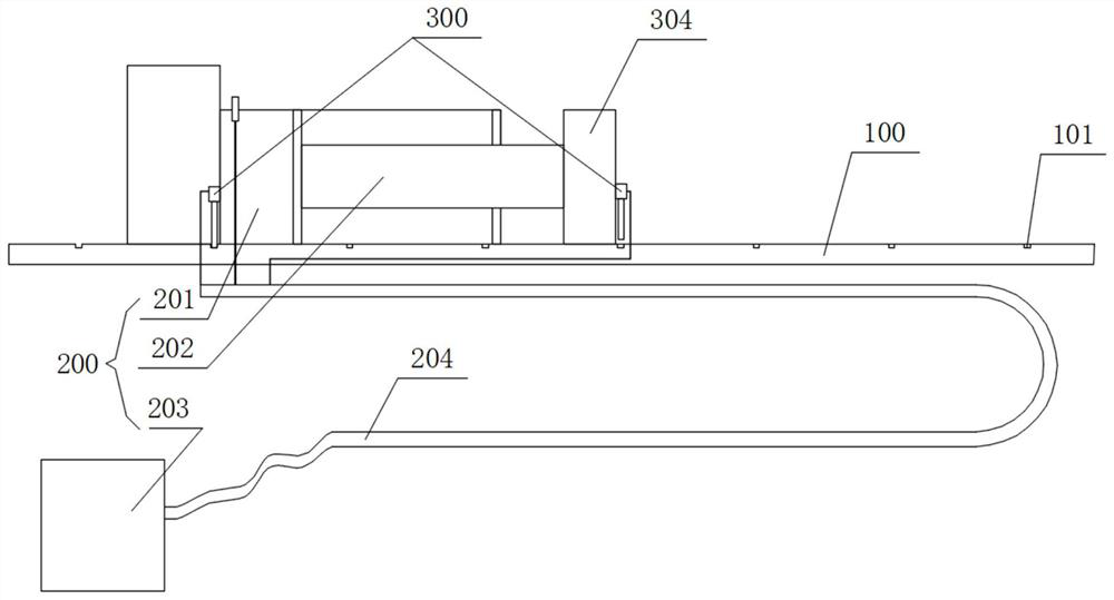
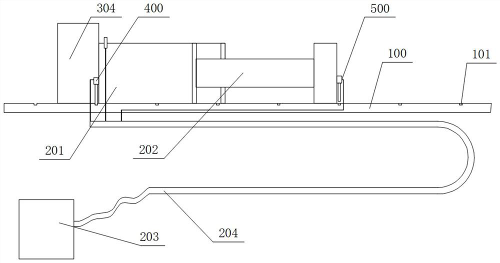
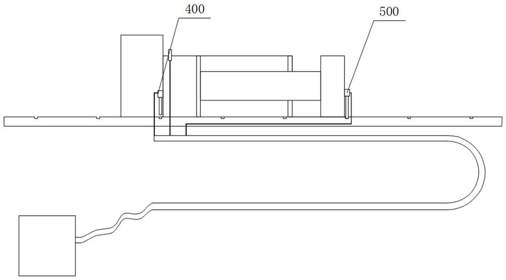
[0051] This embodiment discloses a control method for a hydraulic traveling device, which is applied to the hydraulic traveling device in Embodiment 1. Refer to Figure 5 , including the following steps:
[0052] Step 1: Connect the first positioning mechanism 400 to the positioning part at the corresponding position, and separate the second positioning mechanism 500 from the positioning part at the corresponding position.
[0053] Step 2: Make the first piston rod 202 of the hydraulic mechanism 200 stretch out until the second positioning mechanism 500 is aligned with a positioning portion, so that the hydraulic mechanism 200 maintains the current state.
[0054] Step 3: Connect the second positioning mechanism 500 to the positioning part at the corresponding position, and separate the first positioning mechanism 400 from the positioning part at the corresponding position.
[0055] Step 4: Shrink the first piston rod 202 of the hydraulic mechanism 200, at this time the first...
PUM
 Abstract
Description
Claims
Application Information