Large-current electromagnetic switch

An electromagnetic switch and high-current technology, applied in the field of high-current electromagnetic switches, can solve the problems of inaccurate sampling, complex structure, and insufficient sealing of the device, and achieve the effects of simplified structure, reasonable and compact device structure, and easy sealing

Pending Publication Date: 2021-12-28
XINXIANG GUANGMING ELECTRIC APPLIANCE CO LTD
View PDF1 Cites 0 Cited by
  • Summary
  • Abstract
  • Description
  • Claims
  • Application Information

AI Technical Summary

Problems solved by technology

[0003] The invention provides a high-current electromagnetic switch to solve the technical pr

Method used


Image

  • Large-current electromagnetic switch
  • Large-current electromagnetic switch
  • Large-current electromagnetic switch

Examples


Embodiment 1

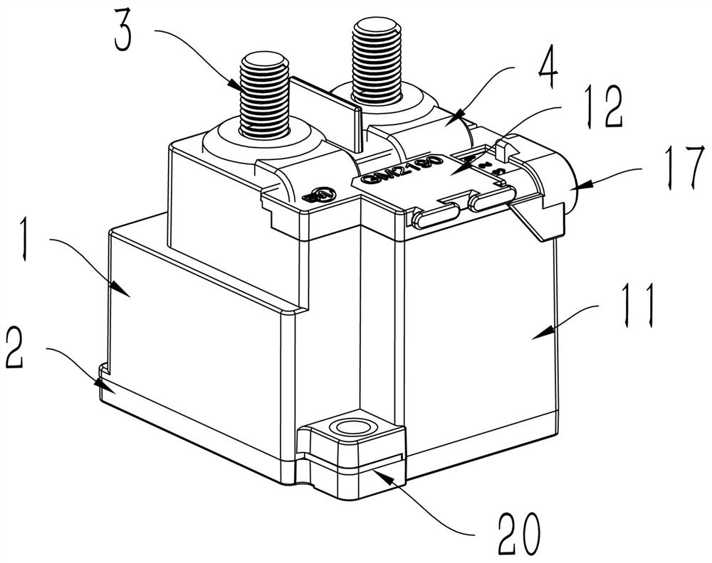
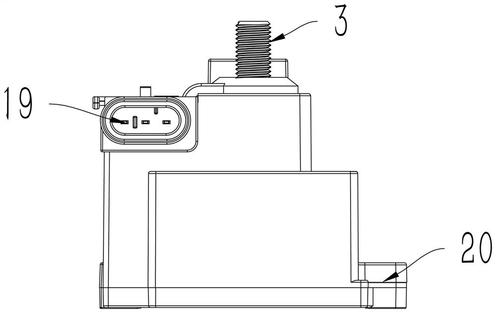
[0026] Embodiment 1: a kind of high-current electromagnetic switch, see Figure 1 to Figure 5 , including a housing 1, a coil 10 and a contact 6 are arranged inside the housing 1, the contact 6 includes a conductive horizontal plate and protrusions at both ends, a spring 7 is connected under the conductive horizontal plate, and an insulating Mounting plate 5. A terminal post 3 is installed on the top surface of the housing 1, and the terminal post 3 passes through the top surface of the housing 1 and is fixed thereon. When the switch is turned on, the contact 6 is in contact with the bottom of the terminal 3. At this time, the current flows from the terminal on the left through the conductive horizontal plate of the contact 6 to the terminal on the right to form a path. When the switch needs to be disconnected, Feed current into the coil 10 to generate a magnetic field, attract the contact 6 downward to separate the contact 6 from the terminal 3, and cut off the circuit.

[...

Embodiment 2

[0032] Example 2: see Image 6 , basically the same as Embodiment 1, the difference is that the circuit board can be designed as two pieces, respectively a control board 91 and a detection board 92, the control board 91 is arranged vertically and the detection board 92 can be arranged horizontally, which can be adjusted according to the actual situation Wiring.

Embodiment 3

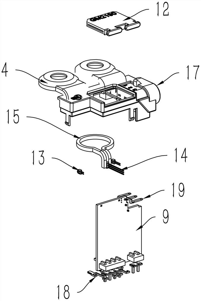
[0033] Embodiment 3: On the basis of Embodiment 1, the copper sheet 4, current sampling ring 15, temperature sensor 13, and current sensor 14 are omitted, that is, all detection elements are removed, and only the main structure of the switch is retained, including the housing 1, The isolation compartment 11, the control circuit board 9, the pins 19, the cover plate 12, and the coil 10, contacts 7, and terminal posts 3 in the housing 1 can save costs, and use the isolation compartment to isolate the circuit board from the contacts in the housing Open to prevent the moisture in the glue injected on the circuit board from diffusing into the contact compartment.


PUM


Abstract

The invention discloses a large-current electromagnetic switch to solve the technical problems that an existing device is inaccurate in sampling, complex in structure and insufficient in sealing performance. The large-current electromagnetic switch comprises a shell, a coil, a contact and a binding post, the binding post is arranged at the top of the shell and comprises an exposed part located outside the shell and an embedded part located in the shell, the coil and the contact are arranged in the shell, the contact corresponds to the embedded part of the binding post, and the coil is used for attracting the contact to enable the contact to be separated from the binding post. The large-current electromagnetic switch further comprises an isolation bin, a control panel and a sensor assembly, the isolation bin is arranged on the side face of the shell, the control panel is arranged in the isolation bin, the sensor assembly is installed in the shell, and a connecting wire of the sensor assembly penetrates through the side face of the shell to be connected to the control panel. The large-current electromagnetic switch has the advantages of being compact in structure, high in sealing performance, accurate in detection data and high in environment adaptability.

Description

technical field [0001] The invention relates to the technical field of on-board relays, in particular to a high-current electromagnetic switch. Background technique [0002] The electromagnetic switch is a device that controls the on-off of the circuit. The coil attracts the contact to separate it from the terminal to disconnect the circuit. In order to detect the working state of the switch, the Chinese patent document with the publication number CN103681108A proposes a high-current electromagnetic relay, which inserts and fixes a sampling assembly on the steps on both sides of an energy-saving high-current electromagnetic relay, and the sampling assembly An electronic sensor circuit board is installed on one side of the inner wall, and there are two temperature sampling connection rings and a current sampling magnetic conduction ring respectively connected to two wiring copper posts on the circuit board, and a temperature control circuit is arranged on the circuit board ,...

Claims


Application Information

Patent Timeline
IPC IPC(8): H01H36/00H01H50/14H01H50/44
CPCH01H36/0033H01H50/14H01H50/44
Inventor 胡广举徐志海孔令宾刘洋
Owner XINXIANG GUANGMING ELECTRIC APPLIANCE CO LTD
Why Eureka
Try Eureka