Transcatheter heart valve replacement system

A heart valve replacement and catheter technology, applied in the field of medical devices, can solve problems such as compression of the native valve annulus and valve leaflets blocking the outflow tract, and achieve the effects of reducing complications, reducing regurgitation, and avoiding obstruction

Pending Publication Date: 2021-12-31
NINGBO JENSCARE BIOTECHNOLOGY CO LTD
View PDF4 Cites 10 Cited by
  • Summary
  • Abstract
  • Description
  • Claims
  • Application Information

AI Technical Summary

Problems solved by technology

[0010] In terms of the application of atrioventricular valve surgery, this application aims to provide a transcatheter heart valve replacement system for patients with atrioventricular valve disease and needs interventional therapy, so as to solve the problems caused by the original heart valve annulus in the heart valve replacement system in the prior art. Cause problems such as compression and valve leaflets blocking the outflow tract

Method used


Image

  • Transcatheter heart valve replacement system
  • Transcatheter heart valve replacement system
  • Transcatheter heart valve replacement system

Examples


Embodiment 2

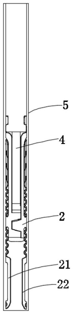
[0077] The second embodiment is basically the same as the first embodiment, except that the repair mechanism 2 in this embodiment also includes an anchor ring 3, wherein the anchor ring 3 cooperates with the valve support 1 to anchor with the native valve leaflet.

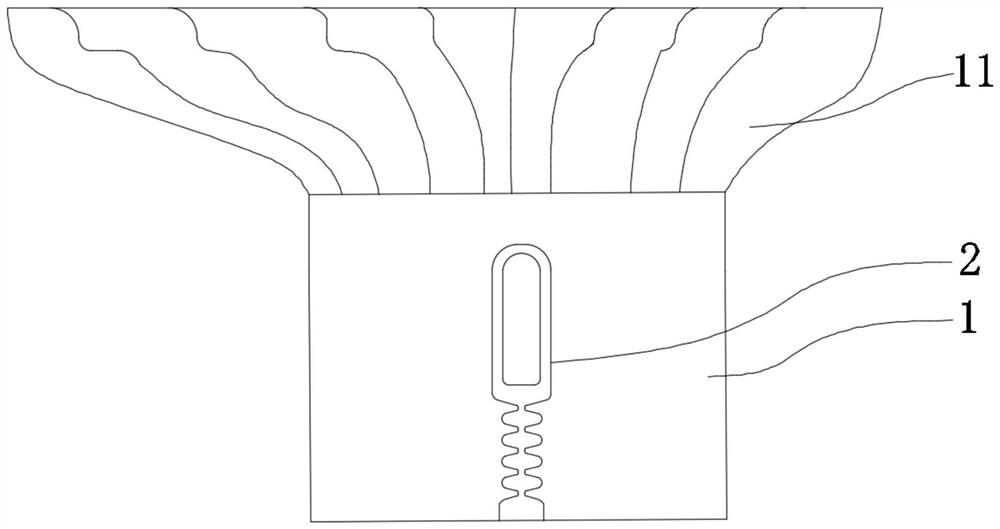
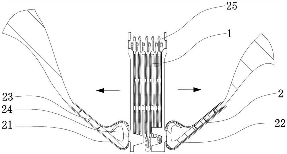
[0078] Such as Figure 5a As shown, in this embodiment, it includes a valve support 1, which has a preset shape; and a repair mechanism 2, which is configured to be located in the middle region of the native valve and used to clip the native valve leaflet; wherein, the repair mechanism 2 includes The first clamping device 21 and the second clamping device 22; and the anchor ring 3, the anchor ring 3 is fixedly connected with the repair mechanism 2; wherein, when the repair mechanism 2 captures and clamps the native leaflet , the anchoring ring 3 is at the periphery of the native valve leaflet and surrounds the native valve leaflet, and the valve support 1 is located in the middle area of ​​the repair mechanism 2; w...

Embodiment 3

[0095] The third embodiment is substantially the same as the second embodiment, except that the repair mechanism 2 in this embodiment also includes an atrium fixing part 26 .

[0096] Such as Figure 7a As shown, in this embodiment, it includes a valve support 1, which has a preset shape; and a repair mechanism 2, which is configured to be located in the middle region of the native valve and used to clip the native valve leaflet; wherein, the repair mechanism 2 includes The first clamping device 21 and the second clamping device 22; the repair mechanism 2 includes an atrium fixing part 26, and the atrium fixing part 26 is configured to adapt to the shape of the annulus physiological structure, and the atrium fixing part 26 is respectively connected with The first clamping device 21 and the second clamping device 22 are fixedly connected, and the anchor ring 3, and the anchor ring 3 is connected with the first clamping device 21 and the second clamping device 22 respectively; w...


PUM


Abstract

The invention relates to the field of medical apparatuses and instruments, in particular to a transcatheter heart valve replacement system. The transcatheter heart valve replacement system comprises a valve stent with a preset shape, and a repairing mechanism; the repairing mechanism is constructed to be located in the middle area of an autologous valve and used for clamping an autologous valve leaflet; in addition, the repairing mechanism has two forms of capturing and separating, wherein when the repairing mechanism is in the capturing form and clamps the autologous valve leaflet, the valve stent is located in the middle area of the repairing mechanism, and the valve stent is restored to be in the preset form and promotes the repairing mechanism to be detached and separated; before the valve stent replaced according to the scheme is implanted, the autologous valve can still work normally, more time is won for an operation, and complications are effectively reduced; and the valve stent can smoothly reach the middle area of the repairing mechanism along a guide inner core, positioning is accurate, operation is more convenient and faster, when the valve stent gradually expands in the radial direction to recover the preset form, the repairing mechanism is separated and surrounds the periphery of the valve stent, and implantation is completed.

Description

technical field [0001] The present application relates to the field of medical devices, in particular to a transcatheter heart valve replacement system. Background technique [0002] From the perspective of heart structure, both the mitral valve and the tricuspid valve have a special physiological structure, which makes it very difficult to accurately position and fix the product. In particular, the position of the mitral valve in the heart and its complex anatomical structure bring great challenges to mitral valve replacement. [0003] Most of the technical methods of anchoring in the prior art use the radial support force of the stent to the atrioventricular annulus. The disadvantage of this technique is that it is easy to cause compression on the tissue around the valve annulus, and it is easy to cause the impact of the stent and the compressed tissue on the outflow tract. In the long run, as the regurgitation decreases, the ventricular and atrial pressures decrease, an...

Claims


Application Information

Patent Timeline
Patent Type & Authority Applications(China)
IPC IPC(8): A61F2/24
CPCA61F2/243A61F2/2409
Inventor 吕世文张晓燕陈进雄
Owner NINGBO JENSCARE BIOTECHNOLOGY CO LTD
Why Eureka
Try Eureka