Welding equipment for continuous splicing of plates and welding method thereof

A technology for welding equipment and plates, which is applied in the direction of welding equipment, auxiliary welding equipment, welding/cutting auxiliary equipment, etc., can solve the problems of insufficient welding strength and affect the welding quality of plates, and achieve the effect of improving stability and reducing frictional resistance

Inactive Publication Date: 2021-12-31
浙江九树机械有限公司
View PDF1 Cites 1 Cited by
  • Summary
  • Abstract
  • Description
  • Claims
  • Application Information

AI Technical Summary

Problems solved by technology

[0004] Although the above-mentioned welding device improves the stability of clamping the plate during welding, usually a single welding head can be used for welding, but if the plate to be welded is thick, only one welding head is used for welding on one side , it is easy to make the welding strength insufficient and affect the welding quality of the plate

Method used


Image

  • Welding equipment for continuous splicing of plates and welding method thereof
  • Welding equipment for continuous splicing of plates and welding method thereof
  • Welding equipment for continuous splicing of plates and welding method thereof

Examples


Embodiment 1

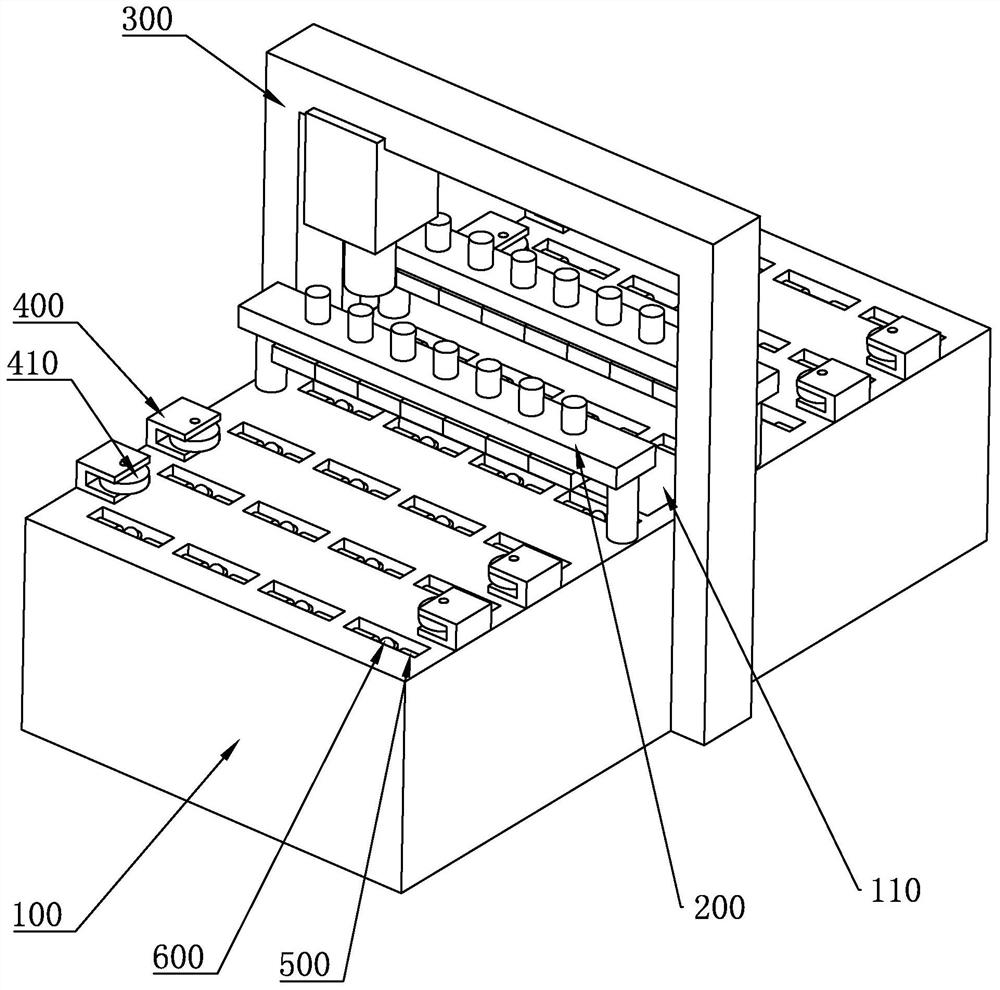
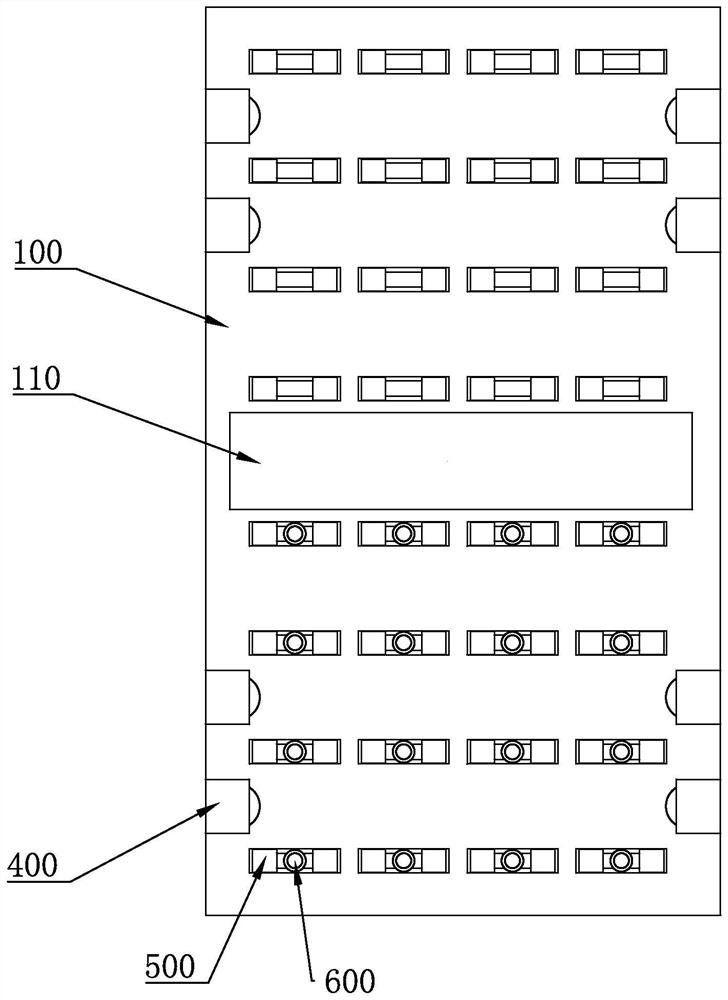
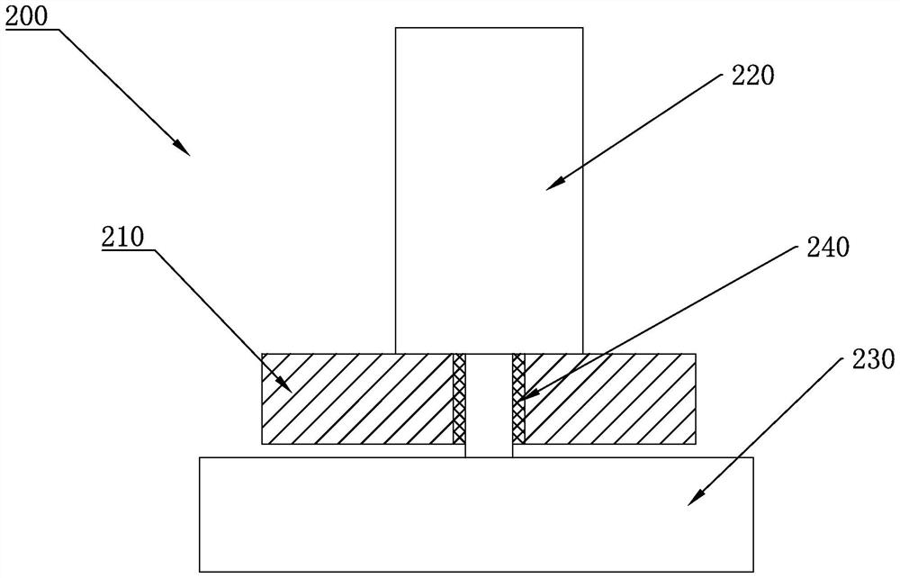
[0048] like figure 1 , figure 2 , image 3 , Figure 4 As shown, the embodiment of the present application provides a welding equipment for continuous splicing of plates, including: a welding table 100, a welding slot 110 is provided in the middle of the welding table 100, the plate is placed on the upper surface of the welding table 100, and the plate Placed on both sides of the welding slot 110 respectively, the gap between the plates is placed above the welding slot 110; the pressing device 200, the pressing device 200 is placed on both sides of the welding slot 110 and corresponds to the plate, The compression device 200 includes a compression seat 210, a compression cylinder 220, a compression member 230, and a guide sleeve 240. The compression cylinder 220 is installed on the compression seat 210, and the compression member 230 is installed on the compression cylinder 220. The guide sleeve 240 is installed on the compression seat 210 and is adapted to the expansion r...

Embodiment 2

[0051] like Figure 5 As shown, the embodiment of the present application provides a welding equipment for continuous splicing of plates. In addition to the above-mentioned technical features, it further includes: a limit movable seat 400, which is placed on both sides of the welding table 100 The sides are evenly distributed; the limit roller 410, the limit movable seat 400 is connected with the limit roller 410 through a rotating shaft; the rack 420, the rack 420 is connected with the limit movable seat 400; the gear 430, the gear 430 is meshed with the corresponding two racks 420, the gear 430 rotates to drive the rack 420 to move, and when the gear 430 rotates, the corresponding limit movable seat 400 moves relatively or in the opposite direction at the same time; the drive motor 440, the drive The motor 440 is installed on the welding table 100 , and the gear 430 is installed on the output shaft of the driving motor 440 .

[0052] The limit movable seat 400 is movably inst...

Embodiment 3

[0054] like Image 6 As shown, the embodiment of the present application provides a welding equipment for continuous splicing of plates. In addition to the above-mentioned technical features, it further includes: a conveying device 500, which is evenly distributed on the welding table 100, and the The conveying device 500 includes a conveying installation seat 510, a conveying roller 520, and a hydraulic cylinder 530. The conveying roller 520 is connected to the conveying installation seat 510 through a bearing, and the hydraulic cylinder 530 is placed between the conveying installation seat 510 and the welding table 100. ; the adjustment device 600, the adjustment device 600 is placed on one side of the welding slot 110, and is movably installed on the delivery installation seat 510, the adjustment device 600 drives the plate to move, and adjusts the size of the gap between the two plates; , the delivery installation seat 510 is provided with an installation groove 511 , and ...


PUM


Abstract

The invention discloses welding equipment for continuous splicing of plates, and belongs to the technical field of welding equipment. According to the key point of the technical scheme, the welding equipment comprises a welding table top, pressing devices and a welding device, and a welding groove hole is formed in the middle of the welding table top; the pressing devices are arranged on the two sides of the welding groove hole and correspond to the plates, each pressing device comprises a pressing seat, a pressing air cylinder, a pressing piece and a guide sleeve, the pressing air cylinders are installed on the pressing seats, the pressing pieces are installed on telescopic rods of the pressing air cylinders, and the guide sleeves are installed on the pressing seats and matched with the telescopic rods of the pressing air cylinders; and the welding device comprises a first welding machine head, a second welding machine head and a portal frame, the first welding machine head is arranged above the plates, and the second welding machine head is arranged below the plates. According to the welding equipment, the two sides of plate gaps are welded, and the welding strength between the plates is improved.

Description

technical field [0001] The application belongs to the technical field of plate laser welding, and in particular relates to a welding device and a welding method for continuous splicing of plates. Background technique [0002] When it is necessary to use metal sheets larger than the established specifications in production, it is necessary to splice the sheets, and in some working conditions, multiple splicing is required to meet the requirements. [0003] The existing Chinese patent with the publication number CN105562950B discloses a laser welding fixture for pressure vessels, which includes a welding workbench, a lower supporting mechanism, an upper pressing mechanism and a follow-up pressing mechanism; The middle support mechanism, the worktable panel rises when welding, and the rolling body rises when feeding, which can make the feeding process smoother and prevent the surface of the workbench panel from being worn; the lower support mechanism cooperates with the upper p...

Claims


Application Information

Patent Timeline
Patent Type & Authority Applications(China)
IPC IPC(8): B23K37/04B23K37/00B23K37/02
CPCB23K37/0408B23K37/00B23K37/02
Inventor 不公告发明人
Owner 浙江九树机械有限公司
Why Eureka
Try Eureka