Hot laminating machine and hot laminating method

A laminating machine and heat laminating technology, which is applied to household components, household appliances, and other household appliances, can solve the problems of manual participation, low operation efficiency, and leather products are easy to get dirty, so as to reduce the chance of contamination and improve The effect of the processing effect

Pending Publication Date: 2021-12-31
KUNSHAN LIANTAO ELECTRONICS CO LTD
View PDF0 Cites 1 Cited by
  • Summary
  • Abstract
  • Description
  • Claims
  • Application Information

AI Technical Summary

Problems solved by technology

[0004] It can be seen that the hot pressing method of the leather layer in the prior art has low operating efficiency, requires m

Method used


Image

  • Hot laminating machine and hot laminating method
  • Hot laminating machine and hot laminating method
  • Hot laminating machine and hot laminating method

Examples


Embodiment 1

[0041] This embodiment provides a thermal bonding machine for processing decorative parts of electronic products, which has high processing efficiency, requires fewer workers, and reduces the probability of contamination of the first material or the second material. Exemplarily, the decorative part in this embodiment may be a leather layer, etc., which is not limited in this embodiment.

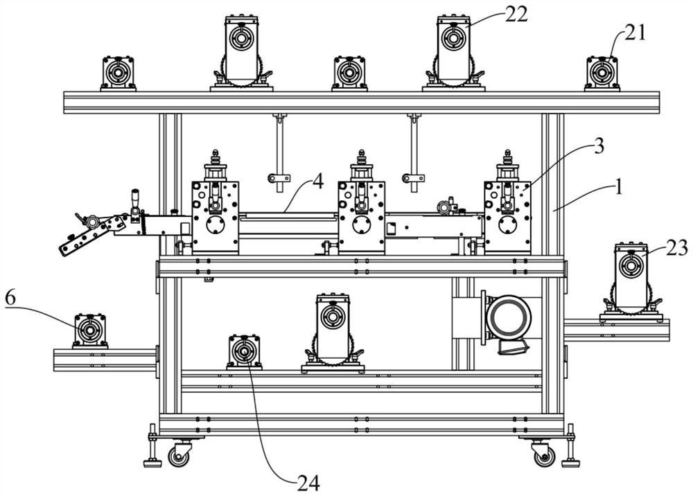
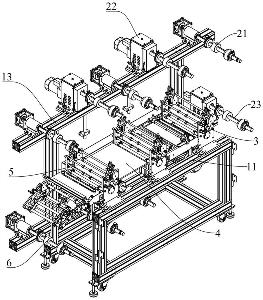
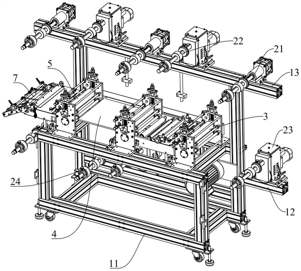
[0042] Such as figure 1 As shown, the heat laminating machine includes a support assembly 1, and a retractable and unwinding assembly, a flattening assembly 3 and a heating assembly 4 respectively arranged on the support assembly 1 .

[0043] Among them, see figure 1, The receiving and discharging assembly includes a first discharging member 21 , a first receiving member 22 and a second discharging member 23 respectively arranged on the support assembly 1 . The first discharging member 21 is used for discharging the first material, so that the first material can be discharged continuously. ...

Embodiment 2

[0059] This embodiment provides a thermal lamination method, which is applied to the thermal lamination machine in Embodiment 1, and has the advantages of high efficiency and fewer required workers.

[0060] Such as Figure 5 As shown, the heat bonding method includes the following steps:

[0061] S1. Hang the roll-shaped first material on the first discharge member, and the first protective film is attached to the first material.

[0062] In this embodiment, hanging the roll-shaped first material on the first discharge member 21 is specifically setting the roll-shaped first material on the first rotating shaft of the first discharge member 21 .

[0063] S2. Hang the rolled second material on the second discharging member.

[0064] In this embodiment, hanging the roll-shaped second material on the second discharge member 23 is specifically setting the roll-shaped second material on the third rotating shaft of the second discharge member 23 .

[0065]S3. Pull the first mater...


PUM


Abstract

The invention discloses a hot laminating machine and a hot laminating method, and belongs to the technical field of electronic product decorating part machining. The hot laminating machine comprises a supporting component, a material receiving and discharging component, a flattening component and a heating component, the material receiving and discharging component comprises a first material discharging part, a first material receiving part and a second material discharging part, the first material discharging part is used for discharging a first material, the first material receiving part is used for winding a first protective film attached to the first material, and the second material discharging part is used for discharging a second material; the flattening component is arranged on the supporting component, and the flattening component is used for flattening the first material and the second material; and the heating component is arranged on the supporting component and located on the downstream of the flattening component, and the heating component is used for heating the flattened first material and the flattened second material and bonding the first material and the second material. The hot laminating machine and the hot laminating method provided by the invention have higher machining efficiency, need fewer operators, and reduce the probability that the first material or the second material is polluted.

Description

technical field [0001] The invention relates to the technical field of electronic product decorative parts processing, in particular to a heat bonding machine and a heat bonding method. Background technique [0002] At present, the shells of electronic products such as wireless chargers and mobile phones include plastic shells and leather layers fixed on the plastic shells. The setting of the leather layer prevents the hands from icy hands when the electronic products are used in cold places. [0003] In the prior art, the leather layer includes leather, heat-pressure-sensitive adhesive and cloth. Because the leather has stretchability, the manufacturing method of the leather layer is die-cutting step by step, and the thermal bonding of leather and heat-pressure-sensitive adhesive and cloth is It is manually operated step by step on the machine. Specifically, the manufacturing process of the leather layer in the prior art is: first cut the large roll of leather into small r...

Claims


Application Information

Patent Timeline
IPC IPC(8): B29C65/18B29C65/48B29C65/78B29L31/34
CPCB29C65/18B29C65/4805B29C65/7858B29C66/1122B29C66/45B29C66/83241B29C66/0224B29L2031/3481
Inventor 吕伟潘琦
Owner KUNSHAN LIANTAO ELECTRONICS CO LTD
Why Eureka
Try Eureka