Blow-off system for orbit control engine ground test

A technology for rail-controlled engines and ground tests, which is applied to engine testing, piping systems, and testing of machine/structural components, etc. Air entrained combustion and other problems, to achieve good blowing effect, isolation safety, low cost effect

Active Publication Date: 2021-12-31
SHANGHAI INST OF SPACE PROPULSION
View PDF16 Cites 2 Cited by
  • Summary
  • Abstract
  • Description
  • Claims
  • Application Information

AI Technical Summary

Problems solved by technology

In fact, for scheme A, the solenoid valve or electromagnetic pneumatic valve may be reversed by the instantaneous pressure peak generated when the orbit control engine is turned on and off, resulting in mixing of oxygen and combustible propellant upstream of the blow-off valve. , it will burn or even explode
For option B, if the instantaneous pressure peak generated when the rail control engine is started is too high, the spool of the self-locking valve may be flushed open by the instantaneous pressure peak, changing from the closed position to the open position, and it is difficult to detect and take measures in time , causing the blow-off gas to enter the orbital control engine to cause entrainment combustion, which deviates from the rated working conditions and damages the product
Although the probability of failure can be reduced by tightening product quality control, there is no guarantee that the blow-off valve will always be closed when it should not be opened. Therefore, Option B still has risks in occasions where reliability requirements are particularly high

Method used


Image

  • Blow-off system for orbit control engine ground test
  • Blow-off system for orbit control engine ground test

Examples


Embodiment 1

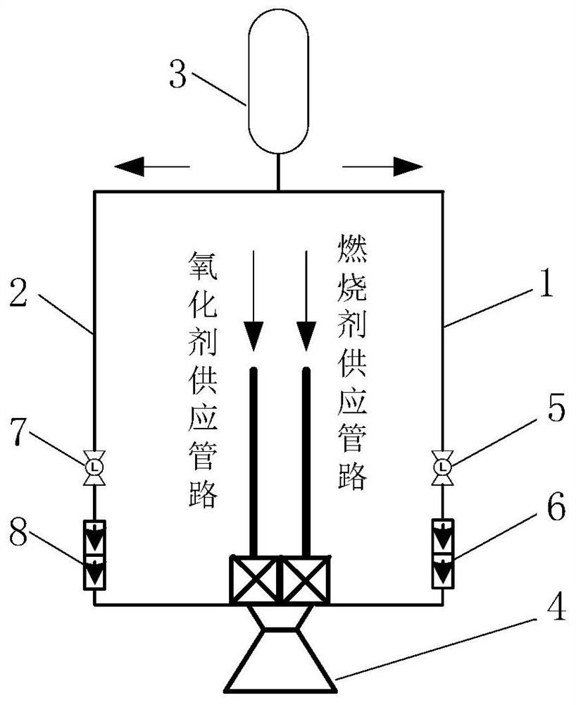
[0048] The invention provides a blow-off system for the ground test of an orbital control engine, such as figure 1 As shown, there are respectively a combustion agent blow-off pipeline 1 and an oxidant blow-off pipeline 2 between the blow-off gas source 3 and the orbit control engine 4, and the combustion agent blow-off pipeline 1 is used for the combustion agent in the orbit control engine 4. Blow-off, the oxidant blow-off pipeline 2 is used to blow off the oxidant in the rail control engine 4, along the direction of the output gas flow of the blow-off gas source 3, the combustion agent blow-off pipeline 1 is sequentially provided with a first control Valve 5, first one-way valve 6, second control valve 7, second one-way valve 8 are arranged on the oxidant blowing pipeline 2 in sequence.

[0049] The first control valve 5 and the second control valve 7 adopt pneumatic valves or electric valves, and the first one-way valve 6 and the second one-way valve 8 are preferably electr...

Embodiment 2

[0056] This embodiment is a preferred example of Embodiment 1.

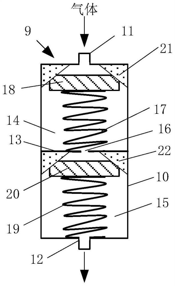
[0057] In this embodiment, the first one-way valve 6 and the second one-way valve 8 both use a double-seat one-way flow control valve 9, such as figure 2 As shown, the double-seat one-way flow control valve 9 includes a control valve housing 10 and an inlet port 11 and an outlet port 12 respectively arranged at both ends of the control valve housing 10. The inlet port 11 is connected to the first port through a pipeline. The control valve 5 or the second control valve 7 is connected, and the outlet port 12 is connected with the orbit control engine 4 through a pipeline.

[0058] The inside of the control valve housing 10 is provided with a partition 13 and the partition 13 divides the inside of the control valve housing 10 into a first chamber 14 and a second chamber 15 communicating with each other, the first chamber The interior of the chamber 14 is provided with a first core structure, and the interior of th...


PUM


Abstract

The invention provides a blow-off system for an orbit control engine ground test. A combustion agent blow-off pipeline and an oxidant blow-off pipeline are respectively arranged between a blow-off gas source and an orbit control engine, a first control valve and a first one-way valve are sequentially arranged on the combustion agent blow-off pipeline in the flowing direction of output gas of the blow-off gas source, and a second control valve and a second one-way valve are sequentially arranged on the oxidant blow-off pipeline. A double-valve-seat one-way flow control valve is arranged at the downstream of a blow-off control valve, so that a valve core of the blow-off control valve cannot be changed in position due to the start-up or shutdown pressure peak of the orbit control engine, and isolation of oxygen and combustion propellants in the blow-off system is safer and more reliable.

Description

technical field [0001] The invention relates to the field of spacecraft propulsion technology, in particular to a blow-off system for ground tests of orbital control engines. Background technique [0002] After the liquid propellant orbital control engine is shut down, there is still a lot of liquid propellant in the head cavity. If the residual propellant is not blown off, it will continue to burn for a long time, which may ablate the injector and endanger the safety of the engine. Therefore, it is very necessary to blow off the orbital control engine. [0003] When the liquid rocket orbital control engine is turned on or off, it usually produces a very high instantaneous pressure peak in the combustion chamber and the propellant pipeline. In extreme cases, it will have a great impact on the pipelines and valves connected to the orbital control engine. , there may be problems such as seal failure, propellant leakage, or abnormal changes in the switch state of the blow-off ...

Claims


Application Information

Patent Timeline
Patent Type & Authority Applications(China)
IPC IPC(8): F17D1/02F17D3/01F17D3/14G01M15/02
CPCF17D1/02F17D3/01F17D3/14G01M15/02
Inventor 韩泉东王浩卫佳叶青孙迎霞何壮睿周一彬
Owner SHANGHAI INST OF SPACE PROPULSION
Why Eureka
Try Eureka