
Dust removal method and system for primary flue gas of converter

A dust removal system and flue gas technology, applied in the manufacture of converters, etc., can solve the problems of aggravated equipment polar plate polar line corrosion, exceeding the standard, and low dust removal effect, so as to reduce the water content of the liquid, reduce the dust content, and ensure the dust removal effect. Effect

Pending Publication Date: 2021-03-05
MCC CAPITAL ENGINEERING & RESEARCH
View PDF8 Cites 2 Cited by
  • Summary
  • Abstract
  • Description
  • Claims
  • Application Information

AI Technical Summary

Problems solved by technology

[0008] In this technology, the wet electrostatic precipitator is placed in front of the post-venturi tube dehydrator of the traditional wet dedusting system. After the flue gas passes through the venturi tube for dedusting, the flue gas contains a large number of liquid water droplets, and these water droplets contain dust particles and some harmful substances. Chemical elements not only increase the workload of the follow-up wet electrostatic precipitator, but also increase the corrosion of the equipment, especially the polar line of the electrode plate; this technology prevents gas explosion by interlocking the high-voltage power supply with the converter oxygen lance, and reduces the Power supply voltage to a safe area, so as to avoid sparks, but in this control mode, due to the low voltage of the high-voltage power supply of the dust collector at the initial stage of oxygen blowing, the dust removal effect will be low, and the dust content in the converter flue gas at this time It is very high, so the dust content at the outlet of the electrostatic precipitator will exceed the standard in the initial stage of oxygen blowing, and it cannot meet the ultra-low emission standard

Method used


Image

  • Dust removal method and system for primary flue gas of converter
  • Dust removal method and system for primary flue gas of converter

Examples


Embodiment Construction

[0062] In order to illustrate the present invention more clearly, the present invention will be further described below in conjunction with preferred embodiments. Those skilled in the art should understand that the content specifically described below is illustrative rather than restrictive, and should not limit the protection scope of the present invention.

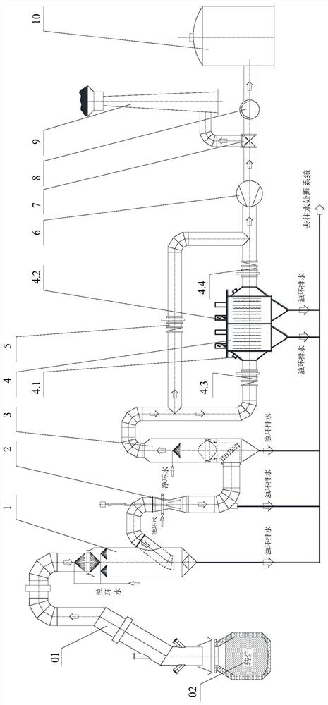
[0063] The present invention provides a preferred embodiment, such as figure 1 As shown, a converter primary flue gas dedusting system includes a sequentially connected spray tower 1, annular venturi tube 2, dehydrator 3, wet electrostatic precipitator 4 and dust removal fan 6; the dust removal fan 6 passes through a three-way valve 7 is respectively connected to release chimney 9 and gas cabinet 10.

[0064] Among them, the wet electrostatic precipitator 4 is arranged after the dehydrator 3 and before the dust removal fan 6, so that the liquid water content of the flue gas entering the wet electrostatic precipitator 4 ...


PUM


Abstract

The invention discloses a dust removal method and system for primary flue gas of a converter. The method comprises the following steps that the primary flue gas enters a spray tower through an evaporative cooling flue to be subjected to cooling and rough dust removal; the flue gas obtained after rough dust removal enters a circular seam venturi tube to be subjected to fine dust removal; the flue gas obtained after fine dust removal enters a dehydrator to be dehydrated; the dehydrated flue gas enters a wet electrostatic precipitator to be subjected to ultrafine dust removal; and the flue gas obtained after ultrafine dust removal enters a gas holder to be stored if meeting recovery conditions, and the flue gas is ignited and then discharged into the atmosphere through a diffusion chimney ifnot meeting the recovery conditions. According to the method, wet electrostatic precipitation is utilized to improve trapping of ultrafine dust, the particle emission concentration of the primary fluegas of the converter does not exceed 10 mg / Nm<3>, and the requirement for ultralow emission is met; meanwhile, the anti-explosion wet electrostatic precipitator is arranged behind the dehydrator; anda gradient oxygen blowing model is adopted in combination with fan flow control, so that the safety and reliability of a process system are ensured.

Description

technical field [0001] The invention belongs to the technical field of metallurgical dedusting, and in particular relates to a method and system for primary flue gas dedusting of a converter. Background technique [0002] During the production process of the converter, a large amount of dusty gas is produced, namely primary flue gas, and the dust content can be as high as 100g / Nm 3 , if it is directly discharged into the atmosphere without purification, it will cause serious air pollution. [0003] There are three technologies for primary flue gas dedusting of traditional converters, namely wet dedusting, semi-dry dedusting and dry dedusting, among which wet dedusting accounts for more than half in China, and the design index of particulate matter emission is 50mg / Nm 3 , after the system has been in operation for a period of time, the particulate matter emission concentration will increase to a certain extent. [0004] The publication number is CN104894329A, and the invent...

Claims


Application Information

Patent Timeline
IPC IPC(8): C21C5/40
CPCC21C5/40
Inventor 鲁亮任乐郝景章徐蕾陈明张传波
Owner MCC CAPITAL ENGINEERING & RESEARCH
Learn More