Fixed tail speed reduction device

A terminal velocity and deceleration parachute technology, which is applied in the field of constant velocity deceleration devices and fixed terminal velocity deceleration devices, can solve the problems of low parachute terminal velocity, reduced penetration capability of body detonation warheads, and failure to meet actual combat needs, so as to achieve guaranteed The effect of power

Active Publication Date: 2021-12-31
XIAN MODERN CHEM RES INST
View PDF7 Cites 2 Cited by
  • Summary
  • Abstract
  • Description
  • Claims
  • Application Information

AI Technical Summary

Problems solved by technology

However, the terminal velocity of the parachute is too low (about 30m / s), and the penetration capability of the body detonation warhead drops too much, which does not meet the needs of actual combat.

Method used


Image

  • Fixed tail speed reduction device

Examples


Embodiment 1

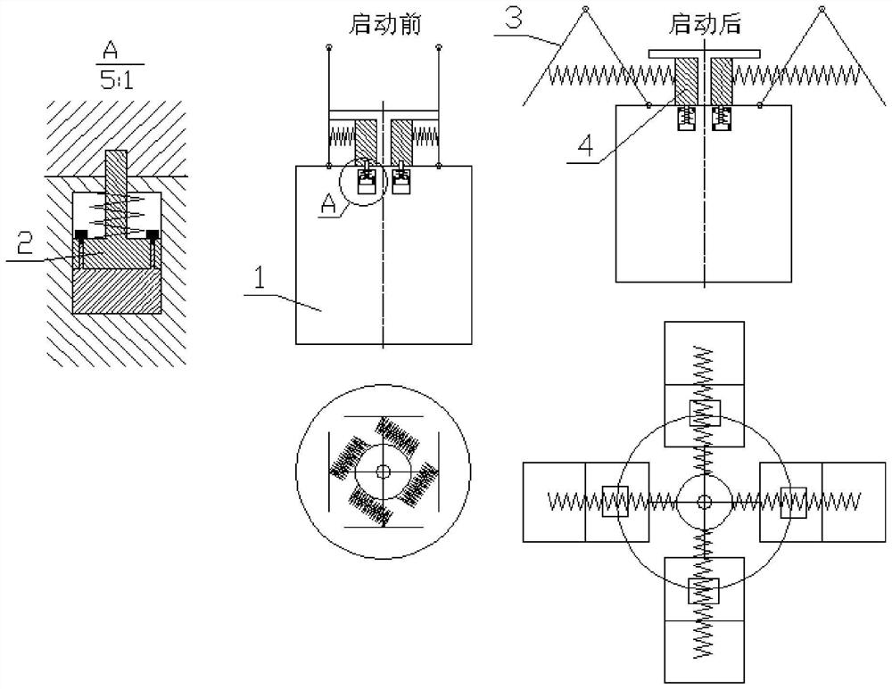
[0031] Such as figure 1 As shown, the present embodiment provides a fixed-end speed reduction device, which includes a body detonation warhead shell 1, which is filled with high-energy fuel inside the body detonation warhead shell 1, and also includes a timing start positioning pin 2, a fixed-end Speed ​​deceleration parachute 3, rotating energy storage device 4, wherein:

[0032] The shape of the body detonation warhead casing 1 is a first cylinder, and the first cylinder is a body of revolution. The direction is the direction of motion of the body detonation warhead shell 1;

[0033] There is a first cylindrical boss in the center of the upper end surface of the first cylinder of the body detonation warhead shell 1, and the outer surface of the first cylindrical boss has four first rectangular bosses uniformly distributed in the circumferential direction. The upper end surface of the first cylinder of the body detonation warhead shell 1 has two left and right symmetrical f...

Embodiment 2

[0069] The difference between the final speed reduction device of this embodiment and that of Embodiment 1 is that the weight of the second plug is 1.6 kg. Others are all the same as in Example 1.

[0070] Process ten above-mentioned constant speed deceleration devices of the present embodiment, test according to the assembly and use method of the fixed speed deceleration device, through live ammunition launch, the speed of body detonation warhead casing 1 when approaching the target is all at 200m / s Within ±17m / s, the speed error is not more than 10%, which meets the use requirements of the body detonation warhead in actual combat, and proves that the final speed deceleration device of this embodiment is effective.

[0071] Therefore, the technical effect brought about by the final speed deceleration device given in this embodiment is embodied as follows:

[0072] The constant speed deceleration parachute starts when the shell of the body detonation warhead is close to the t...


PUM


Abstract

The invention discloses a fixed tail speed reduction device. The fixed tail speed reduction device comprises a body detonation warhead shell body, a timing starting positioning pin, fixed tail speed brake parachutes and a rotary energy storage device, the upper end of a second cylindrical boss of the timing starting positioning pin is located in a fourth blind hole of the rotary energy storage device, the middle of the outer side face of a fourth cylinder of the rotary energy storage device is connected with four springs evenly distributed in the circumferential direction, the other ends of the four springs are connected with the centers of third rectangular plates, away from the axis of a rotary body of the body detonation warhead shell body, of the four fixed tail speed brake parachutes respectively, the windward areas of the fixed tail speed brake parachutes correspondingly change along with the speed of a body detonation warhead, when the speed of the body detonation warhead is high, the speed can be greatly reduced within a very short time, and when the speed of the body detonation warhead reaches 200 m/s, the resistance of the body detonation warhead is reduced to be the same as the gravity of the body detonation warhead, and the body detonation warhead moves at a constant speed. The high-energy fuel and the air are mixed to form an active cloud cluster form, so that affect subsequent body detonationis not affected, and it is guaranteed that the power of the body detonation warhead is exerted.

Description

technical field [0001] The invention belongs to the technical field of deceleration devices, and relates to a constant speed deceleration device, in particular to a constant speed deceleration device. Background technique [0002] The interior of the body detonation warhead is filled with high-energy fuel, driven by the explosion and throwing of explosives, the high-energy fuel is thrown into the air, and the high-energy fuel is mixed with the air to form a large-scale active cloud. It produces a body detonation and releases a strong shock wave, which is one of the most powerful weapons. [0003] With the development of anti-aircraft and anti-missile technology, higher requirements are put forward for the penetration capability of the body detonation warhead, and the main way to improve the penetration capability is to increase the speed. The speed of the body detonation warhead can reach supersonic speed. The body detonation warhead can be accelerated by launch tubes, and...

Claims


Application Information

Patent Timeline
Patent Type & Authority Applications(China)
IPC IPC(8): F42B12/52
CPCF42B12/52
Inventor 许志峰袁宝慧曹玉武王世英郭双锋
Owner XIAN MODERN CHEM RES INST
Why Eureka
Try Eureka