

Imaging system, camera module and electronic device
An imaging system and image-side technology, applied in optical components, optics, instruments, etc., can solve the problems of insufficient field of view, limited shooting range, and insufficient imaging surface, and achieve wide-angle, shortened overall length, and large like high effect
- Summary
- Abstract
- Description
- Claims
- Application Information
AI Technical Summary
Problems solved by technology
Method used
Image

Examples
specific Embodiment 1
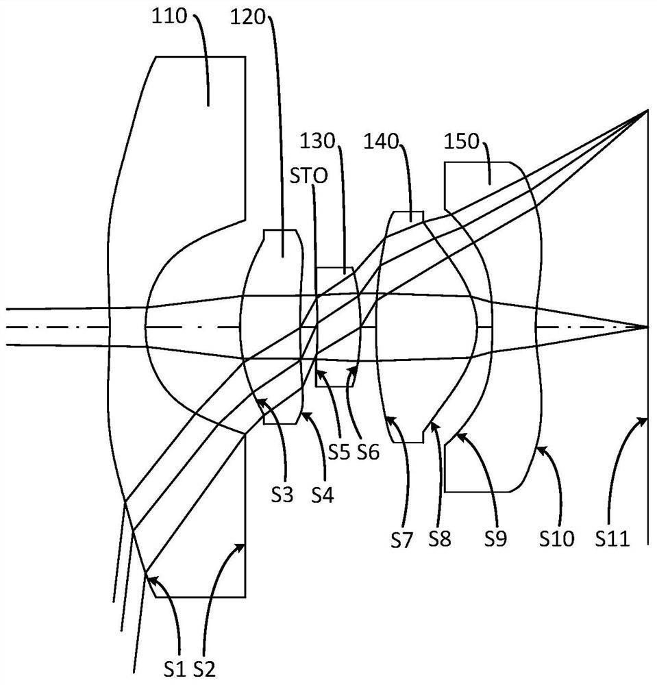
[0086] For a schematic structural diagram of the imaging system 10 of the embodiment of the present application, see figure 1 , the imaging system 10 includes a first lens 110 , a second lens 120 , a stop STO, a third lens 130 , a fourth lens 140 and a fifth lens 150 arranged sequentially along the optical axis from the object side to the image side. The first lens 110 has a negative refractive power, the second lens 120 has a positive refractive power, the third lens 130 has a positive refractive power, the fourth lens 140 has a positive refractive power, and the fifth lens 150 has a negative refractive power. The object side S1 of the first lens 110 is convex at the near optical axis, and the image side S2 of the first lens 110 is concave at the near optical axis. The object side S3 of the second lens 120 is convex at the near optical axis, and the image side S4 of the second lens 120 is concave at the near optical axis. The object side S5 of the third lens 130 is concave a...
specific Embodiment 2
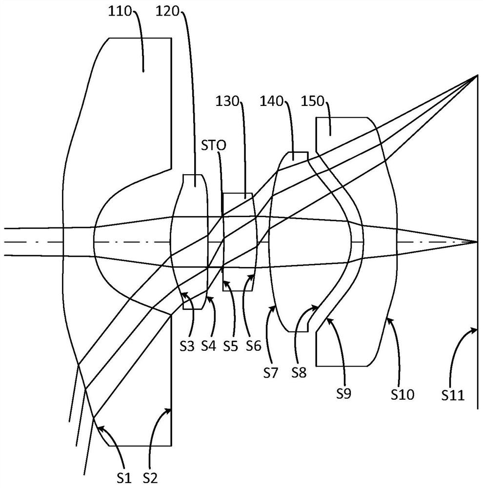
[0101] For a schematic structural diagram of the imaging system 10 of the embodiment of the present application, see image 3 , the imaging system 10 includes a first lens 110 , a second lens 120 , a stop STO, a third lens 130 , a fourth lens 140 and a fifth lens 150 arranged sequentially along the optical axis from the object side to the image side. The first lens 110 has a negative refractive power, the second lens 120 has a positive refractive power, the third lens 130 has a positive refractive power, the fourth lens 140 has a positive refractive power, and the fifth lens 150 has a negative refractive power. The object side S1 of the first lens 110 is convex at the near optical axis, and the image side S2 of the first lens 110 is concave at the near optical axis. The object side S3 of the second lens 120 is convex at the near optical axis, and the image side S4 of the second lens 120 is convex at the near optical axis. The object side S5 of the third lens 130 is concave at...
specific Embodiment 3
[0113] For a schematic structural diagram of the imaging system 10 of the embodiment of the present application, see Figure 5, the imaging system 10 includes a first lens 110 , a second lens 120 , a stop STO, a third lens 130 , a fourth lens 140 and a fifth lens 150 arranged sequentially along the optical axis from the object side to the image side. The first lens 110 has a negative refractive power, the second lens 120 has a positive refractive power, the third lens 130 has a positive refractive power, the fourth lens 140 has a positive refractive power, and the fifth lens 150 has a negative refractive power. The object side S1 of the first lens 110 is convex at the near optical axis, and the image side S2 of the first lens 110 is concave at the near optical axis. The object side S3 of the second lens 120 is convex at the near optical axis, and the image side S4 of the second lens 120 is concave at the near optical axis. The object side S5 of the third lens 130 is concave a...
PUM
 Abstract
Description
Claims
Application Information