
Cutter detection method and device, computer equipment and storage medium

A detection method and tool technology, applied in the field of image processing, can solve the problems of low detection efficiency, cumbersome and time-consuming detection process, etc., and achieve the effect of improving efficiency and reducing frequent disassembly

Pending Publication Date: 2021-12-31
CHINA ELECTRONICS PROD RELIABILITY & ENVIRONMENTAL TESTING RES INST
View PDF0 Cites 0 Cited by
  • Summary
  • Abstract
  • Description
  • Claims
  • Application Information

AI Technical Summary

Problems solved by technology

[0004] However, the machine vision analysis method needs to remove the tools used in the production line and place them on a specific inspection device for defect inspection. The entire inspection process is cumbersome and time-consuming, and there is a problem of low inspection efficiency

Method used


Image

  • Cutter detection method and device, computer equipment and storage medium
  • Cutter detection method and device, computer equipment and storage medium
  • Cutter detection method and device, computer equipment and storage medium

Examples


Embodiment Construction

[0055] In order to make the purpose, technical solution and advantages of the present application clearer, the present application will be further described in detail below in conjunction with the accompanying drawings and embodiments. It should be understood that the specific embodiments described here are only used to explain the present application, and are not intended to limit the present application.

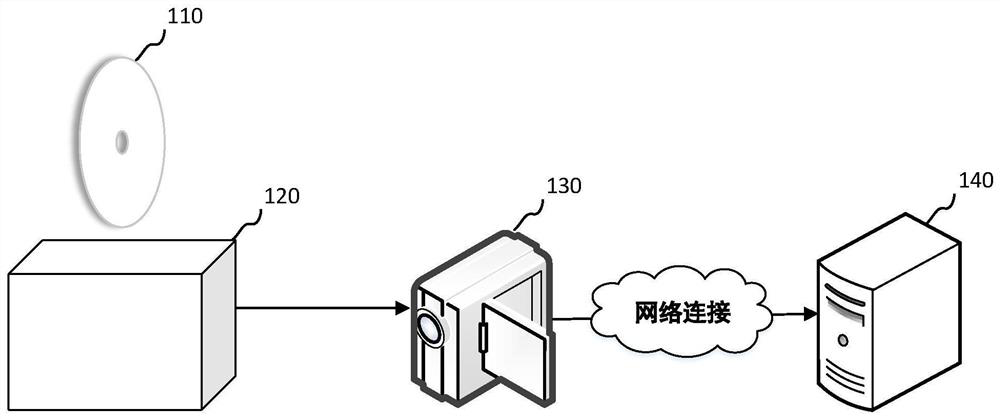
[0056] The tool detection method provided by this application can be applied to such as figure 1 shown in the application environment. The application environment includes a tool 110 , a cutting object 120 , an image acquisition device 130 and a computer device 140 . Wherein, the image acquisition device 130 communicates with the computer device 140 through a network. The computer device 140 may specifically be a terminal or a server. Terminals can be, but are not limited to, various personal computers, notebook computers, smart phones, tablet computers, and portable we...


PUM


Abstract

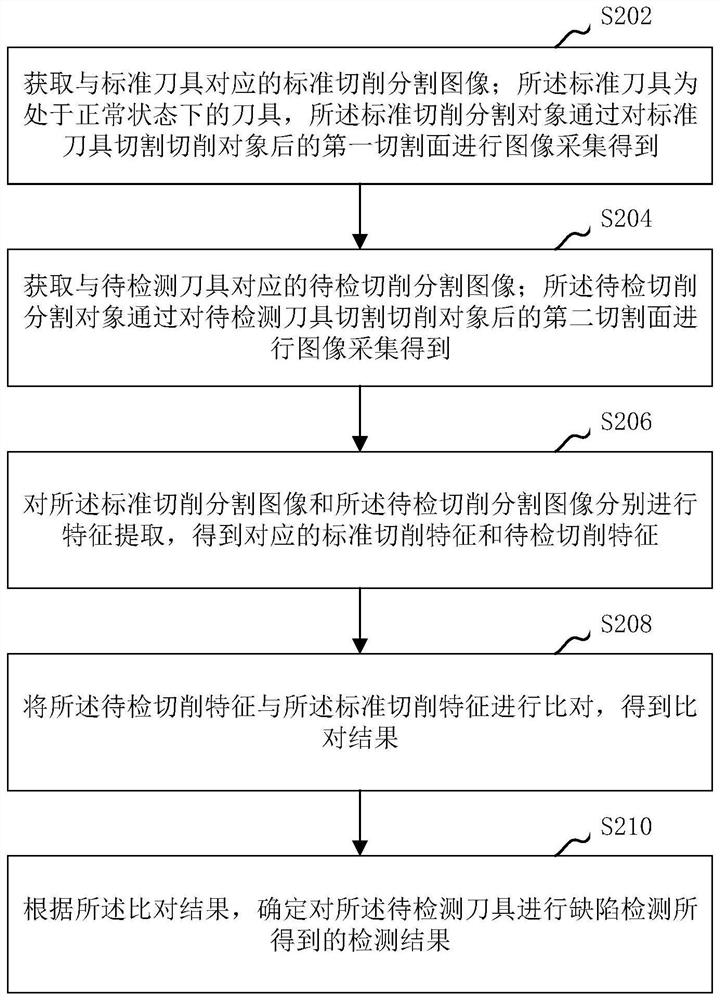
The invention relates to a cutter detection method and device, computer equipment and a storage medium. The method comprises the following steps: acquiring a standard cutting segmentation image corresponding to a standard cutter, wherein the standard cutter is a cutter in a normal state, and the standard cutting segmentation image is obtained by performing image acquisition on a first cutting surface after the cutting object is cut by the standard cutter; obtaining a to-be-detected cutting segmentation image corresponding to a to-be-detected cutter, wherein the to-be-detected cutting segmentation image is obtained by performing image acquisition on a second cutting surface after the cutting object is cut by the to-be-detected cutter; respectively carrying out feature extraction on the standard cutting segmentation image and the to-be-detected cutting segmentation image to obtain a corresponding standard cutting feature and to-be-detected cutting feature; comparing the to-be-detected cutting feature with the standard cutting feature to obtain a comparison result; and according to a comparison result, determining a detection result obtained by performing defect detection on the to-be-detected cutter. By using the method, the cutter defect detection efficiency can be improved.

Description

technical field [0001] The present application relates to the technical field of image processing, in particular to a tool detection method, device, computer equipment and storage medium. Background technique [0002] With the development of aviation, shipbuilding, automobile, chemical industry, electric power, consumer electronics and other fields, various industries have higher and higher requirements for the manufacturing quality of related mechanical products. In the manufacturing process of mechanical products, the cutting precision of the cutting tool is required to be as high as the micron level, so the wear and deformation of the props will seriously affect the qualification of the mechanical product. Based on this, the health status detection of the cutting tool in the process of mechanical product processing appears Very important. [0003] In the traditional technology, the method of machine vision analysis is mainly used to detect and analyze the defects of the ...

Claims


Application Information

Patent Timeline
Patent Type & Authority Applications(China)
IPC IPC(8): G06T7/00G06T7/62G06K9/46
CPCG06T7/0002G06T7/62
Inventor 周振威孙宸黄云何世烈时林林刘俊斌路国光
Owner CHINA ELECTRONICS PROD RELIABILITY & ENVIRONMENTAL TESTING RES INST
Learn More