Eureka AIR delivers breakthrough ideas for toughest innovation challenges, trusted by R&D personnel around the world.

Mold cooling structure for uniformly cooling mold core

A mold cooling and balanced technology, which is applied in the field of mold cooling, can solve the problems of hot stamping on the appearance of products, reduce processing quality, and reduce processing efficiency, so as to improve heat insulation effect, avoid rapid temperature rise, and improve processing efficiency and processing quality Effect

Pending Publication Date: 2022-01-04
SUZHOU CHUNJU ELECTRIC CO LTD
View PDF0 Cites 0 Cited by
  • Summary
  • Abstract
  • Description
  • Claims
  • Application Information

AI Technical Summary

Problems solved by technology

[0003] When designing the cooling water channel of the mold, the cooling water usually uses copper or iron to conduct heat to cool the mold core, which leads to the rapid cooling of the part of the conventional cooling water channel that is close to the water well, but the cooling is not in place far away from the water well. cycle to achieve the ideal mold temperature, which will not only reduce the processing efficiency, but also cause uneven mold temperature during cooling, which will easily cause defects such as watermark hot stamping on the appearance of the product, and reduce the processing quality

Method used


Image

  • Mold cooling structure for uniformly cooling mold core
  • Mold cooling structure for uniformly cooling mold core
  • Mold cooling structure for uniformly cooling mold core

Examples


Embodiment Construction

[0029] The following will clearly and completely describe the technical solutions in the embodiments of the present invention with reference to the accompanying drawings in the embodiments of the present invention. Obviously, the described embodiments are only some, not all, embodiments of the present invention. Based on the embodiments of the present invention, all other embodiments obtained by persons of ordinary skill in the art without creative efforts fall within the protection scope of the present invention.

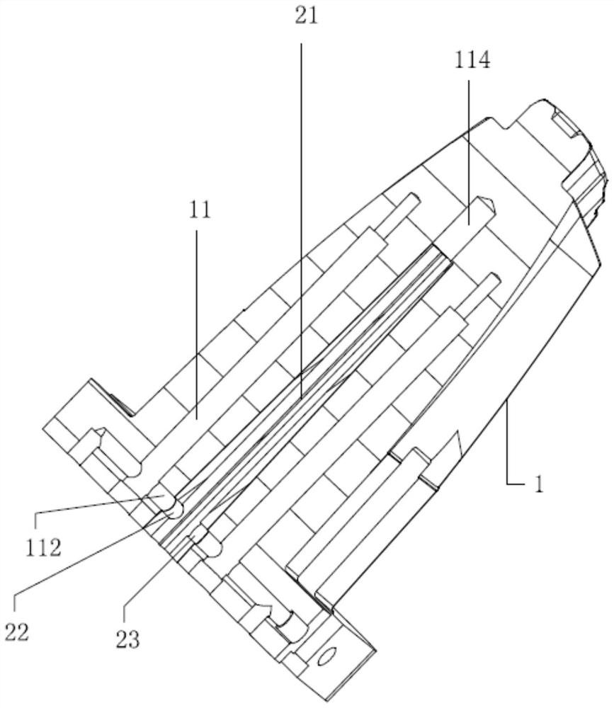
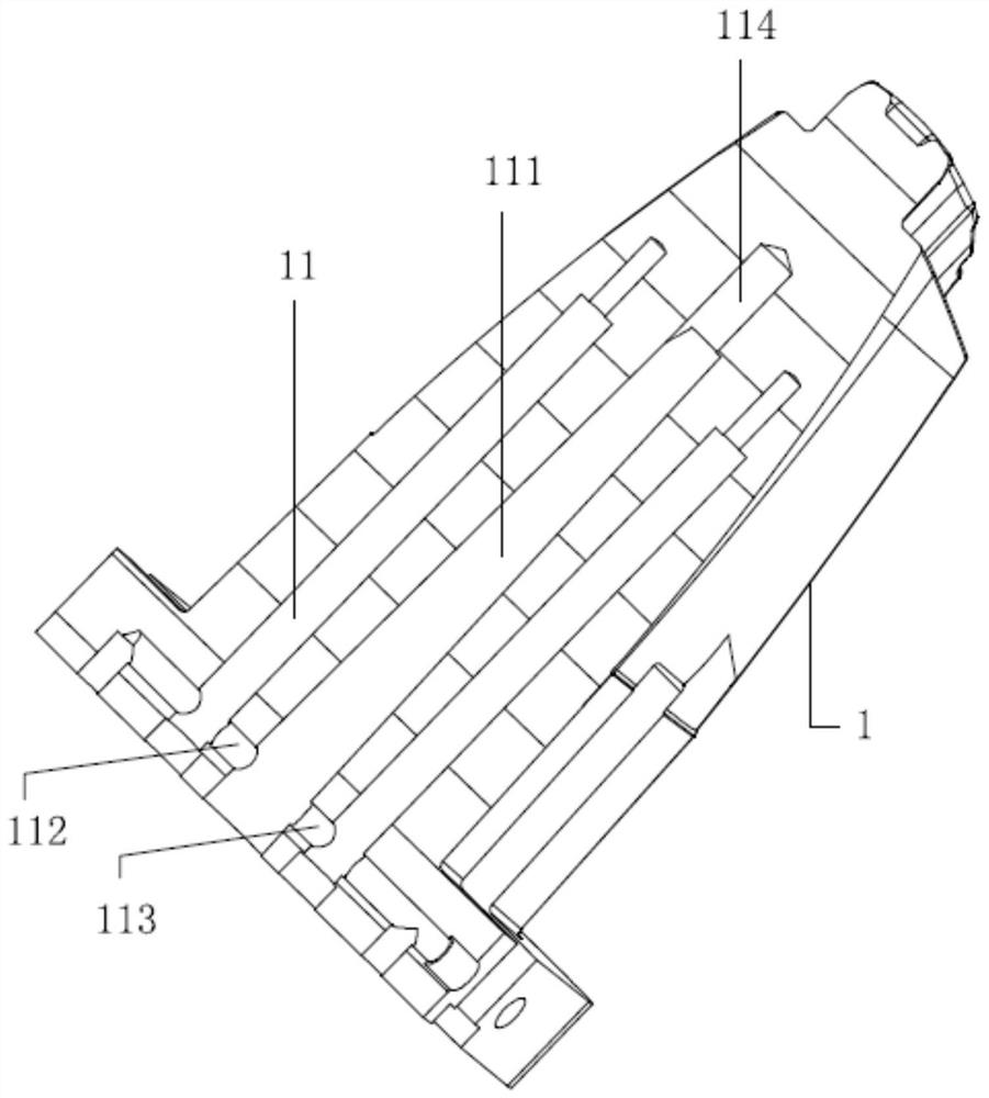
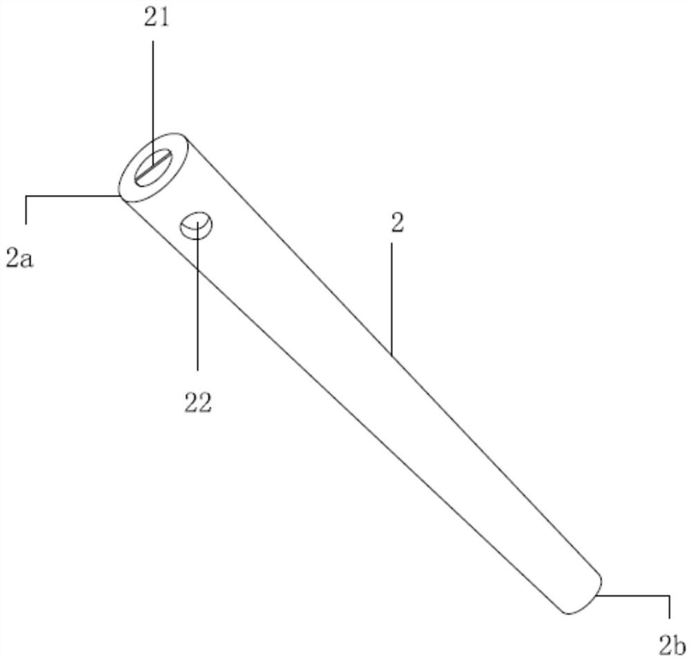
[0030] see Figure 1-3 , the present invention provides a technical solution: a mold cooling structure for balanced cooling of the mold core, including a mold body 1 and a heat insulation pipe 2, a cooling water channel 11 is provided in the mold body 1, and the cooling water channel 11 includes a first cooling channel 111, The first cooling water circulation channel 112 and the second cooling water circulation channel 113, the first cooling water circulation chann...


PUM


Abstract

The invention discloses a mold cooling structure for uniformly cooling a mold core. The structure comprises a mold body and a heat insulation pipe, a cooling water path is arranged in the mold body, and the cooling water path comprises a first cooling channel, a first cooling water circulation channel and a second cooling water circulation channel. The first cooling water circulation channel and the second cooling water circulation channel are symmetrically arranged on the two sides of the first cooling channel, the heat insulation pipe is fixedly installed in the first cooling channel, a partition plate is arranged in the heat insulation pipe, a water passing gap extending towards the interior of the mold body is formed in the bottom face of the first cooling channel, and a water inlet and a water outlet are formed in the heat insulation pipe. The water inlet and the water outlet are symmetrically formed in the two sides of the partition plate, the water inlet communicates with the first cooling water circulation channel, and the water outlet communicates with the second cooling water circulation channel. Compared with the prior art, uniform cooling of the mold core is achieved, and the machining efficiency and the machining quality of products are fully improved.

Description

technical field [0001] The invention belongs to the field of mold cooling, in particular to a mold cooling structure for balanced cooling of mold cores. Background technique [0002] The mold refers to the tool that makes the blank into a workpiece with a specific shape and size under the action of external force. Widely used in blanking, die forging, cold heading, extrusion, powder metallurgy parts pressing, pressure casting, and compression molding or injection molding of engineering plastics, rubber, ceramics and other products. [0003] When designing the cooling water channel of the mold, the cooling water usually uses copper or iron to conduct heat to cool the mold core, which leads to the rapid cooling of the part of the conventional cooling water channel that is close to the water well, but the cooling is not in place far away from the water well. Cycle to achieve the ideal mold temperature, which will not only reduce the processing efficiency, but the uneven mold t...

Claims


Application Information

Patent Timeline
Patent Type & Authority Applications(China)
IPC IPC(8): B29C33/04
CPCB29C33/04
Inventor 臧剑韦彬彬
Owner SUZHOU CHUNJU ELECTRIC CO LTD
Why Eureka
Eureka Blog
Learn More