Compact tire valve of central tire inflation and deflation system
A compact technology for inflation and deflation, which is applied in tire measurement, tire parts, valve lifts, etc. It can solve problems such as low system integration, slow air leakage, and large solenoid valve volume, and achieve enhanced dust-proof effects, Guaranteed pressure holding effect and high integration effect
- Summary
- Abstract
- Description
- Claims
- Application Information
AI Technical Summary
Problems solved by technology
Method used
Image
Examples
Embodiment 1
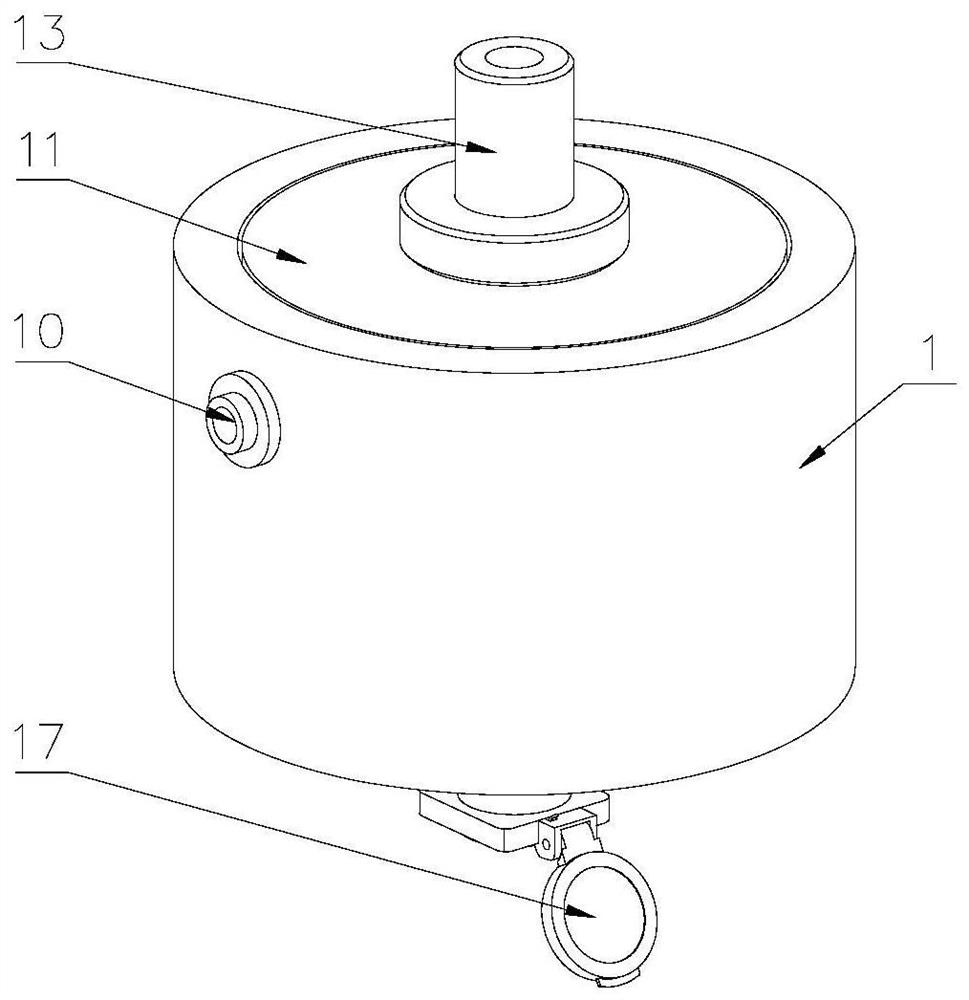
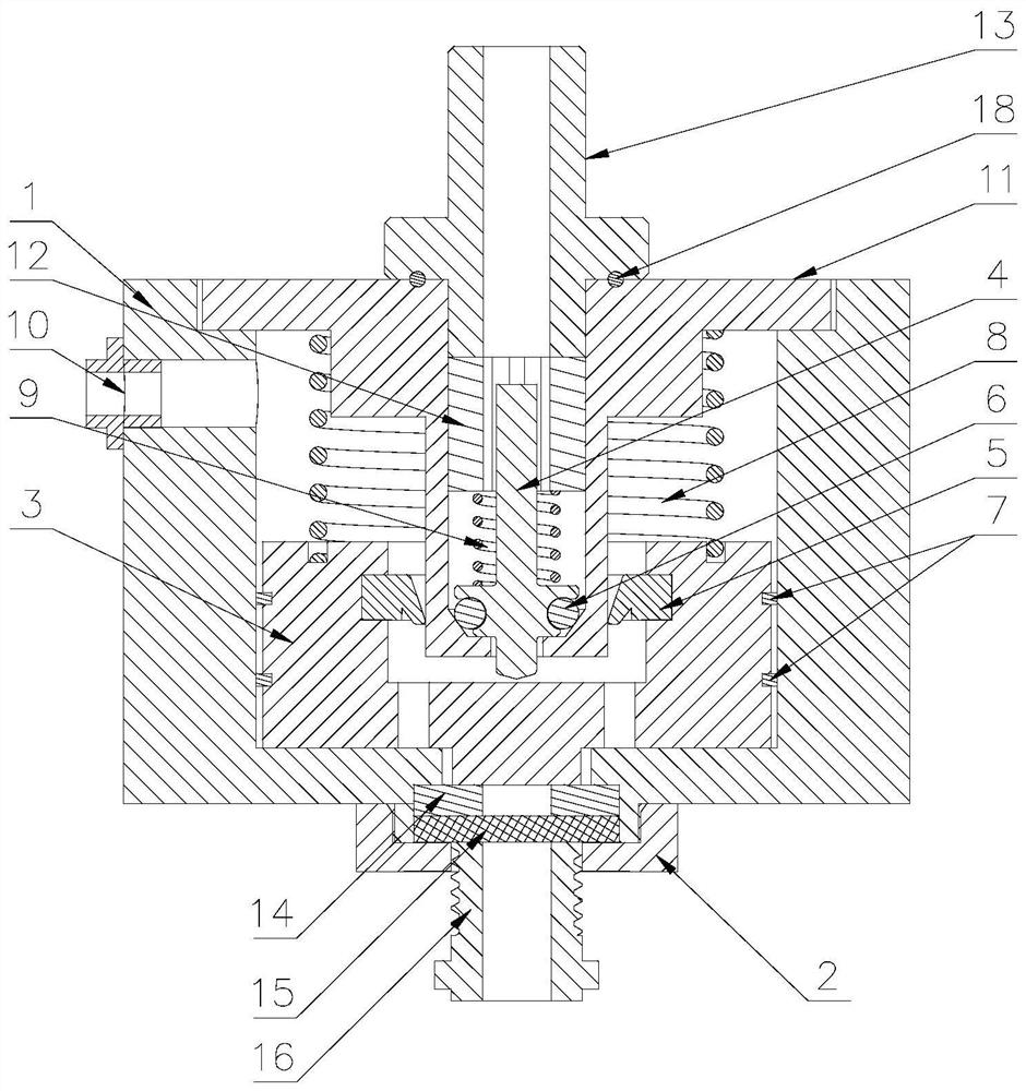
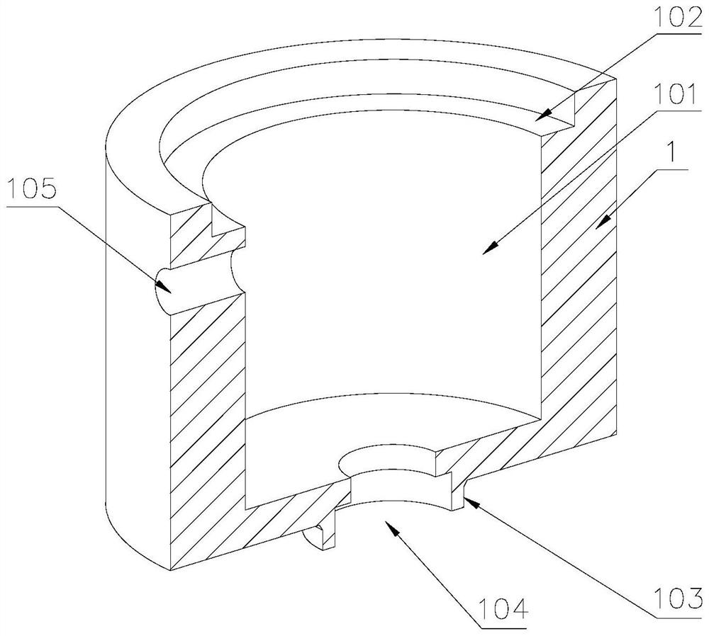
[0045] like Figure 1-7 As shown, a compact central tire inflation and deflation system tire valve includes a valve body 1, a control valve core 3 and a one-way lock valve valve core 4. An air inlet 105 is provided on one side of the valve body 1, and the air inlet The intake joint 10 is installed in 105, the bottom of the valve body 1 is provided with a first boss 103, the lower part of the first boss 103 is provided with an exhaust port 104, the first boss 103 is provided with a stepped hole inside, and the inside of the stepped hole is A second sealing ring 14 is provided, the outside of the first boss 103 is provided with a bottom cover of the valve body 1, the middle of the bottom cover of the valve body 1 is provided with a first through hole 201 that communicates with the second sealing ring 14, and the bottom cover of the valve body 1 is opposite to the bottom cover of the valve body 1. The second sealing ring 14 is fixed; the middle of the valve body 1 is provided wit...
Embodiment 2
[0054] like Figure 11 As shown, the difference from Embodiment 1 is that in this embodiment, the dust-proof member 17 includes a thimble 1705, the front end of the thimble 1705 is a frustum-shaped structure, and the top ring 16 is provided with a stepped hole inside, and the thimble 1705 is provided with a stepped hole. 1705 is arranged inside the stepped hole, there is a gap between the lower part of the thimble 1705 and the wall of the large hole of the stepped hole, the front end of the thimble 1705 is in contact with the lower end of the small hole of the stepped hole, and the lower part of the top ring 16 is threadedly connected with an end cap 1707. There is a ventilation hole in the middle of the cap 1707, and a third spring 1706 is arranged inside the end cap 1707, and the upper end of the third spring 1706 is in contact with the lower part of the thimble 1705; when exhausting, the airflow pushes the thimble 1705 and flows out from the large hole of the stepped hole, a...
Embodiment 3
[0056] like Figure 12 As shown, the difference from Embodiment 1 is that in this embodiment, the bottom cover of the valve body 1 is a U-shaped gusset structure with a through hole on one side, and one end of the gusset plate is threaded with the valve body 1 through screws. The valve body 1 is provided with a positioning gusset 202 on one side, the front end of the bottom cover of the valve body 1 abuts against the inner wall of the positioning gusset 202, and the upper end of the bottom cover of the valve body 1 abuts against the upper wall of the positioning gusset 202. There are guide plates 203 on both sides of the 202. The positioning buckle plate 202 and the guide plate 203 are convenient for the quick positioning and installation of the bottom cover of the valve body 1. The guide plates 203 at both ends form a funnel-shaped structure with a large front opening and a small rear opening.
[0057] at rest, such as Figure 13 As shown, the control spool 3 of the tire va...
PUM
 Abstract
Description
Claims
Application Information
 - R&D
- Intellectual Property
- Life Sciences
- Materials
- Tech Scout
- Unparalleled Data Quality
- Higher Quality Content
- 60% Fewer Hallucinations
Browse by: Latest US Patents, China's latest patents, Technical Efficacy Thesaurus, Application Domain, Technology Topic, Popular Technical Reports.
© 2025 PatSnap. All rights reserved.Legal|Privacy policy|Modern Slavery Act Transparency Statement|Sitemap|About US| Contact US: help@patsnap.com


