Control valve and mechanical linkage pressure switch valve

A technology for controlling valves and pressure, applied in mechanical equipment, diaphragm valves, safety valves, etc., can solve the problems of easy cracks or gaps in the diaphragm, fixed failure of the periphery of the diaphragm, deformation of the diaphragm, etc., to achieve good sealing effect, high pressure The effect of reducing and slowing down the degree of deformation

Pending Publication Date: 2022-01-04
ZHEJIANG RUILI AIR COMPRESSOR EQUIP CO LTD
View PDF6 Cites 0 Cited by
  • Summary
  • Abstract
  • Description
  • Claims
  • Application Information

AI Technical Summary

Problems solved by technology

[0004] However, in the prior art, the elastic member exerts a downward elastic force on the spring seat, and then the spring seat continues to exert downward pressure on the diaphragm, while only the valve plate and the valve body are used as rigid supports under the diaphragm, and it will be used for a period of time. Finally, this kind of structure will easily deform the unsupported part of the diaphragm. After a long time, the deformation will easily cause cracks or gaps in the diaphragm, resulting in air leakage; result in air leakage

Method used


Image

  • Control valve and mechanical linkage pressure switch valve
  • Control valve and mechanical linkage pressure switch valve
  • Control valve and mechanical linkage pressure switch valve

Examples


Embodiment 1

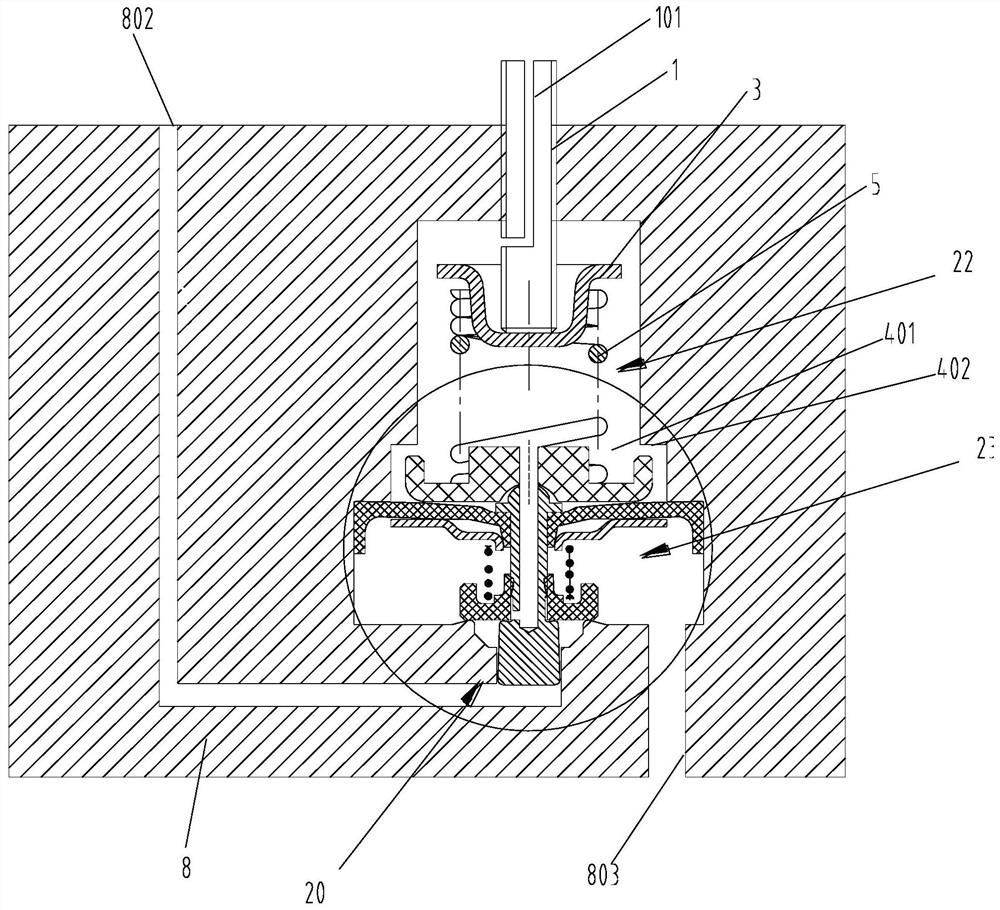
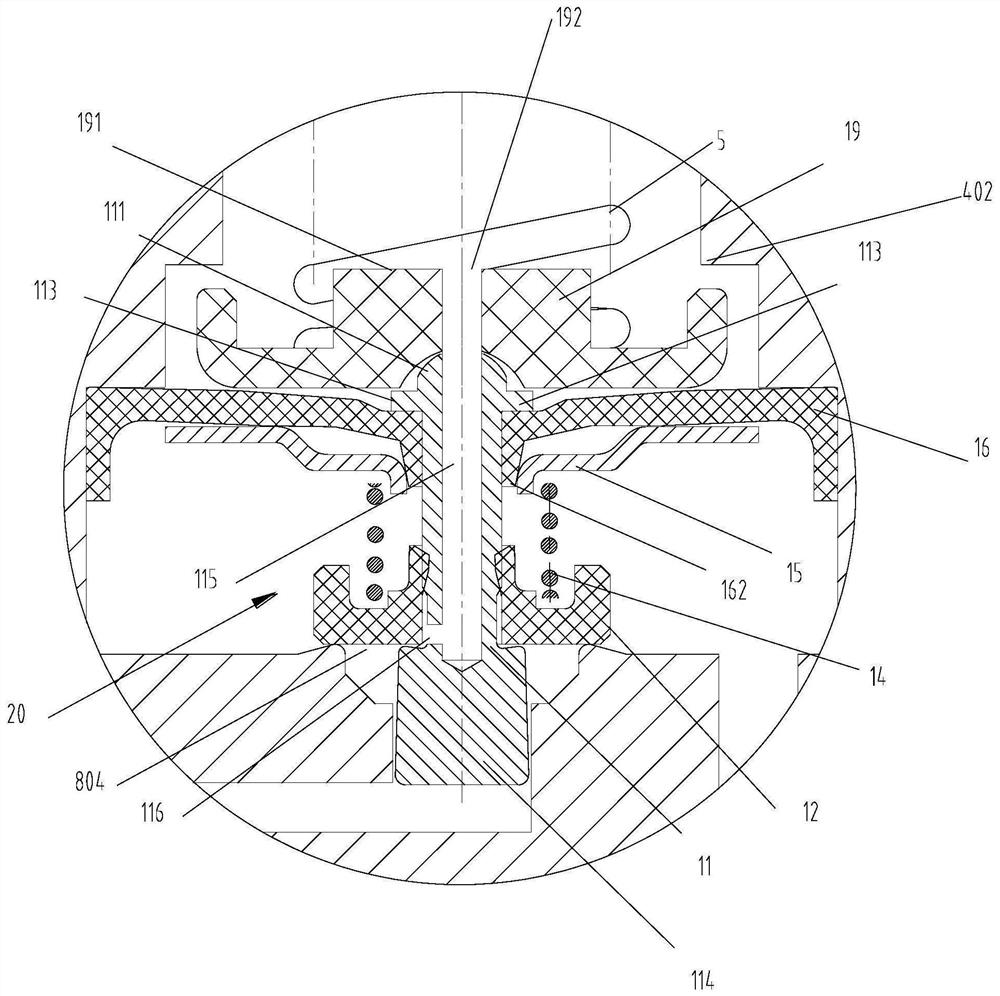
[0045] Such as Figure 1-3 As shown, a control valve includes a valve body 8, a cavity 401 is formed in the valve body 8, a fluid opening 804 is formed at the bottom of the cavity 401, and a valve stem assembly 20, an elastic sealing part 16 and an upper pressure assembly are arranged in the cavity 401 22. The elastic sealing part 16 is used to drive the valve stem assembly 20 to move so that the valve stem assembly 20 blocks or opens the fluid opening 804. The upper pressure assembly 22 is arranged in the cavity 401 above the elastic sealing part 16. The upper pressure assembly 22 is used to adjust The pressure exerted on the elastic sealing part 16 ; it also includes a downward pressure component 23 for buffering the deformation of the elastic sealing part 16 , which is arranged in the cavity 401 below the elastic sealing part 16 .

[0046] Further, in this embodiment, the lower pressure assembly 23 includes a compression spring 14, the compression spring 14 is a coil spring...

Embodiment 2

[0056] further reference Figure 4 , the present application also proposes a mechanical linkage pressure switch valve, which is a modification on the basis of Embodiment 1, the difference is as follows: it also includes a pressure sensor 7, the pressure sensor 7 is installed at the fluid outlet 802, and the pressure sensor 7 is based on The pressure of the fluid outlet 802 is switched off and a signal is output. Specifically, an accommodating chamber 811 is formed at the fluid outlet 802 , and the pressure sensor 7 is disposed in the accommodating chamber 811 .

[0057] Further, the pressure sensor 7 includes an elastically deformable switch diaphragm 701, a small spring 702, an electric contact 703, a terminal 704, and an inner valve body 705; Each side is provided with an electric contact piece 703, the bottom of the inner valve body 705 is connected with a switch diaphragm 701, and the top of the inner valve body 705 abuts against the small spring 702; 802 stretches out, ...


PUM


Abstract

The invention discloses a control valve, which comprises a valve body, a cavity is formed in the valve body, a fluid opening is formed in the bottom of the cavity, a valve rod assembly, an elastic sealing part and an upper pressure assembly are arranged in the cavity, the elastic sealing part is used for driving the valve rod assembly to move so that the valve rod assembly can plug or open the fluid opening, an upper pressure assembly is arranged in the cavity above the elastic sealing part, and the upper pressure assembly is used for adjusting the pressure applied to the elastic sealing part; the control valve further comprises a lower pressure assembly which is used for buffering deformation of the elastic sealing part and is arranged in the cavity below the elastic sealing part. The lower part of the elastic sealing part is changed into elastic support through the added lower pressure assembly, so that the influence of cracks or gaps and the like on the deformed elastic sealing part caused by rigid support is avoided, the peripheral fixation failure of the elastic sealing part is further reduced or avoided, and air leakage is reduced or generated; and the lower pressure assembly also enables a sealing valve plate to be subjected to continuous downward pressure of a pressure spring, so that the sealing effect between the sealing valve plate and the side wall of the fluid opening is better.

Description

technical field [0001] The invention relates to the field of pressure switches, in particular to a control valve and a mechanical linkage pressure switch valve. Background technique [0002] Pressure switches can be widely used in petroleum, chemical industry, metallurgy, electric power, water supply and other fields to measure the pressure of various fluids, which can be divided into parts that feel pressure and parts that switch. [0003] Patent document CN200810161149.2 discloses a pressure regulating valve for vehicle fuel pipeline, which mentions: "The diaphragm is inserted between the upper housing and the lower housing, and the inner valve body is arranged in the diaphragm. The spring seat is set On the diaphragm. The valve plate is attached to the bottom of the inner valve body, and the valve plate opens and closes the valve body set in the bushing", "elastic member, such as a coil spring, is set on the inner valve body for inward The valve body provides elastic for...

Claims


Application Information

Patent Timeline
Patent Type & Authority Applications(China)
IPC IPC(8): F16K17/30F16K37/00F16K7/17
CPCF16K17/30F16K37/0025F16K7/17
Inventor 张仕锡张玄肖超炜章利好
Owner ZHEJIANG RUILI AIR COMPRESSOR EQUIP CO LTD
Why Eureka
Try Eureka