
High-pressure extrusion dehydrator and using method thereof

A squeeze dehydrator, high-pressure technology, applied in dryers, dry solid materials without heating, dry goods processing, etc., can solve the problem of inability to realize multi-directional drainage during the extrusion process, reduce garbage processing time, and complex internal structure, etc. problems, to achieve the effect of improving drainage efficiency, convenient operation and simple structure

Pending Publication Date: 2022-01-04
CHONGQING ENDURANCE & SHINMAYWA IND
View PDF10 Cites 2 Cited by
  • Summary
  • Abstract
  • Description
  • Claims
  • Application Information

AI Technical Summary

Problems solved by technology

[0007] The above-mentioned invention uses the first silo, the second silo, and the third silo to complete the process steps of feeding, extruding, and discharging at the same time on the horizontal plane, so that the time for processing garbage is greatly reduced and the efficiency is increased. However, The internal structure of the above-mentioned equipment is relatively complicated, takes up a large space, and at the same time cannot realize multi-directional drainage during the extrusion process

Method used


Image

  • High-pressure extrusion dehydrator and using method thereof
  • High-pressure extrusion dehydrator and using method thereof
  • High-pressure extrusion dehydrator and using method thereof

Examples


Embodiment 1

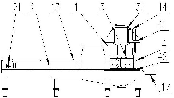
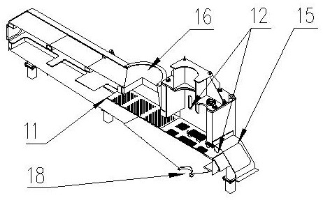
[0052] As a preferred embodiment of the present invention, this embodiment provides a high-pressure extrusion dehydrator, including an extrusion equipment frame 1, a feeding pusher 2 and an extrusion pusher 3, and the two sides of the extrusion equipment frame 1 Set as a feeding part and an extruding part, the feeding push head 2 is arranged in the feeding part, the extruding push head 3 is arranged in the extruding part, and the feeding push head 2 and the extruding push head 3 are both provided with The driving mechanism is provided with a feed inlet 16 above the feeding part, a discharge port 17 is provided on one side of the extrusion part, a water outlet 18 is provided below the extrusion equipment frame 1, and a sealing gate 4 is provided at the extrusion part. The gate is provided with a driving mechanism, the two sides of the extrusion push head 3 are designed with side drainage holes, the bottom surface of the extrusion push head 3 is provided with bottom surface drain...

Embodiment 2

[0055] As another preferred embodiment of the present invention, refer to the attached figure 1 , the present embodiment provides a high-pressure extrusion dehydrator, including an extrusion equipment frame 1, a feeding pusher 2 and an extrusion pusher 3, and the two sides of the extrusion equipment frame 1 are set as a feeding part and an extrusion part, the feeding push head 2 is set in the feeding part, the extrusion push head 3 is set in the extrusion part, the feeding push head 2 and the extrusion push head 3 are both provided with a driving mechanism, and There is a feed port 16, a discharge port 17 is provided on one side of the extruding part, and a water outlet 18 is provided under the extruding equipment frame 1. The extruding part is provided with a sealing gate 4, and a driving mechanism is provided on the gate. Both sides of the extrusion pushing head 3 are designed with side drainage holes, the bottom surface of the extrusion pushing head 3 is provided with botto...

Embodiment 3

[0058] As another preferred embodiment of the present invention, this embodiment provides a high-pressure extrusion dehydrator, including an extrusion equipment frame 1, a feeding pusher 2 and an extrusion pusher 3, the extrusion equipment frame 1 The two sides are set as a feeding part and an extruding part. The feeding pusher 2 is arranged at the feeding part, and the extruding pusher 3 is arranged at the extruding part. The feeding pusher 2 and the extruding pusher 3 are both A drive mechanism is provided, a material inlet 16 is provided above the feeding part, a discharge port 17 is provided on one side of the extruding part, a water outlet 18 is provided under the extruding equipment frame 1, and a sealing gate 4 is provided on the extruding part , the gate is provided with a drive mechanism, the two sides of the extrusion push head 3 are designed with side drainage holes, the bottom surface of the extrusion push head 3 is provided with bottom surface drainage holes, and t...


PUM


Abstract

The invention discloses a high-pressure extrusion dehydrator and a using method thereof, and relates to the field of garbage treatment. The high-pressure extrusion dehydrator comprises an extrusion equipment frame, a feeding push head and an extrusion push head; a feeding part and an extrusion part are arranged on the two sides of the extrusion equipment frame; the feeding push head is arranged on the feeding part and the extrusion push head is arranged on the extrusion part; the feeding push head and the extrusion push head are both provided with a driving mechanism; a feeding opening is arranged at the upper portion of the feeding part; a discharging opening is arranged at one side of the extrusion part; a water outlet is arranged at the lower portion of the extrusion equipment frame; the extrusion part is provided with a sealing gate; the driving mechanisms is arranged on the gate; and side face drainage holes are arranged at the two sides of the extrusion push head; the bottom surface of the extrusion push head is provided with bottom surface drainage holes; and the two sides of the extrusion equipment frame are provided with frame side drainage grooves. According to the high-pressure extrusion dehydrator provided by the invention, multi-direction drainage in the extrusion process is achieved, the overall drainage efficiency is improved, and dry and wet component separation in the extrusion process is achieved.

Description

technical field [0001] The invention relates to the field of garbage treatment, in particular to a high-pressure extrusion dehydrator. Background technique [0002] Kitchen waste and kitchen waste refer to the waste generated in the daily life of residents and activities such as food processing, catering services, and unit meals, including discarded vegetable leaves, leftovers, leftovers, fruit peels, eggshells, tea dregs, Bones, etc., whose main sources are home kitchens, restaurants, restaurants, canteens, markets and other industries related to food processing. [0003] Kitchen waste and food waste contain extremely high moisture and organic matter, which are easy to rot and produce bad smell. After proper treatment and processing, it can be transformed into new resources. The high organic matter content makes it possible to be used as fertilizer and feed after strict treatment, and can also produce biogas for fuel or power generation. The oil part can be used to prepare...

Claims


Application Information

Patent Timeline
Patent Type & Authority Applications(China)
IPC IPC(8): F26B5/14F26B25/00F26B25/12F26B25/18
CPCF26B5/14F26B25/008F26B25/002F26B25/18F26B25/12
Inventor 彭佳周刚黄状陈强牟新玥
Owner CHONGQING ENDURANCE & SHINMAYWA IND
Learn More