Drying device

A drying device, No. 1 technology, applied in the direction of drying, drying machine, drying gas arrangement, etc., can solve the problems of influence, failure to grasp the working status of the drying device in time, and large span required

Active Publication Date: 2022-01-04
江苏东方恒基通用航空有限公司
View PDF11 Cites 2 Cited by
  • Summary
  • Abstract
  • Description
  • Claims
  • Application Information

AI Technical Summary

Problems solved by technology

[0005] In the technical scheme of the prior art, the adjustment of the drying method and mode is realized by real-time monitoring of the temperature / humidity of the drying device, but in the industrial process line of continuous drying process, the drying device often requires The span is large, and setting a large number of sensors to monitor the overall internal temperature / humidity will increase the production cost, and it is impossible to grasp the working conditions of the internal components of the drying device, especially the moving parts, so that it may be due to component failure or failure. And affect the drying effect and even the whole production process

Method used


Image

  • Drying device
  • Drying device
  • Drying device

Examples


Embodiment Construction

[0031] The following detailed description is given in conjunction with the accompanying drawings.

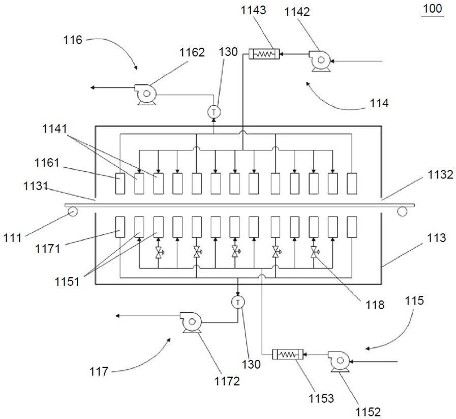
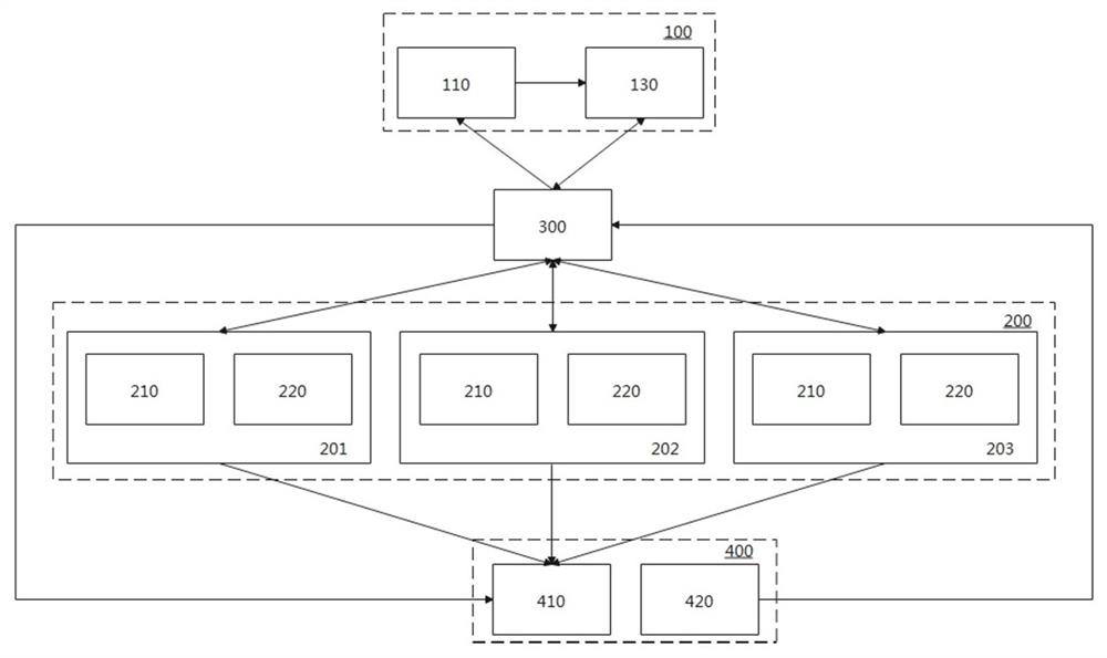
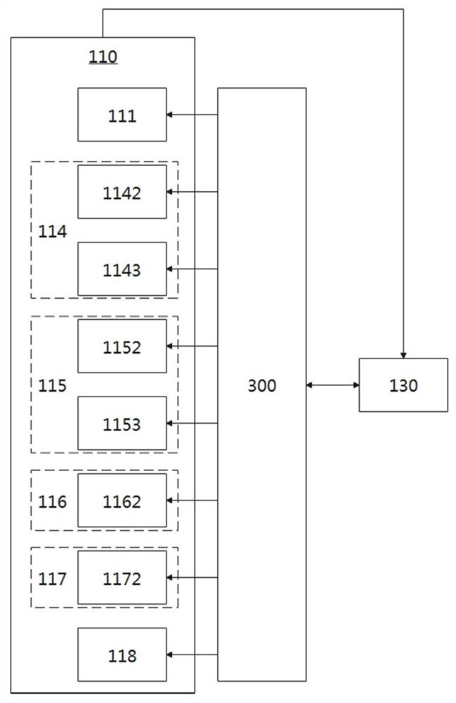
[0032] like figure 1 Shown is a schematic structural diagram of a drying device in a preferred embodiment, such as figure 2 Shown is the signal transmission diagram of the drying device in a preferred embodiment, such as image 3 Shown is a partial signal connection diagram of the drying device of the present invention in a preferred embodiment, such as Figure 4 Shown is a block diagram of the control flow of the drying device of the present invention in a preferred embodiment.

[0033] The present invention discloses a drying device, which at least includes an interrelated main module 100, the main module 100 can establish a signal connection with the auxiliary module 200 through the control module 300, and also includes an auxiliary module 200, and the auxiliary module 200 can be used with at least one The end 400 establishes a signal connection, so that at least bidirect...


PUM


Abstract

The invention relates to a drying device. The device comprises a main body module and an auxiliary module, a drying main body unit of the main body module comprises a transmission assembly and a heating unit, the heating unit is provided with an air inlet mechanism and an exhaust mechanism to dry a solvent contained in a target product, and an induction unit can collect physical and chemical parameters of different parts of the drying main body unit. The auxiliary module can respectively establish an automatic evolution model which at least can change based on time variation and / or position variation through a graphic processing unit and / or a module processing unit, the establishment premise of the automatic evolution model is that the auxiliary module is based on the physical and chemical parameters, acquired by the induction unit, of the drying main body unit, and the auxiliary module can at least adjust a virtual moving part, corresponding to an actual moving part, in the established automatic evolution model in a visual manner according to different change conditions of position variation data of the actual moving part in the drying main body unit in the operation process, wherein the position variation data is acquired by the induction unit.

Description

technical field [0001] The present invention relates to the technical field of drying equipment, in particular to a drying device. Background technique [0002] The drying device is an industrial equipment that generates power through electricity, diesel power, wind power, flammable material power, etc., and uses ambient air to heat, transport it to the surrounding area, and then reach an appropriate temperature for dehumidification treatment. The drying device vaporizes and escapes the moisture in the material (generally refers to moisture or other volatile liquid components) by heating to obtain a solid material with a specified moisture content to meet the needs of material use or further processing. [0003] For example, CN102744189A discloses a special drying device for coating, which is used for transferring and drying the coated substrate, including a box body and a pressing roller assembly arranged in the box body, and the pressing roller assembly is correspondingly ...

Claims


Application Information

Patent Timeline
Patent Type & Authority Applications(China)
IPC IPC(8): F26B15/12F26B21/00F26B21/10F26B25/06G06T11/00G06T15/00G06T17/00
CPCF26B15/12F26B21/001F26B21/004F26B21/10F26B25/06G06T17/00G06T15/00G06T11/001
Inventor 王涛
Owner 江苏东方恒基通用航空有限公司
Why Eureka
Try Eureka