Method for correcting direction-finding coning effect of one-dimensional interferometer

A calibration method and interferometer technology, applied in the field of electronics, can solve the problems that the direction finding accuracy cannot be substantially improved and the application effect is limited, and achieve the effect of improving the accuracy and saving computing resources.

Active Publication Date: 2022-01-04
SOUTHWEST CHINA RES INST OF ELECTRONICS EQUIP
View PDF18 Cites 4 Cited by
  • Summary
  • Abstract
  • Description
  • Claims
  • Application Information

AI Technical Summary

Problems solved by technology

[0003] At present, it is mainly processed by reducing the height difference between the reconnaissance platform and the target, controlling the maneuvering range of the carrier aircraft, and eliminating the direction finding value in the large maneuvering window. It cannot be substantially improved, which limits the application of one-dimensional interferometer direction finding, and the actual application effect is also very limited

Method used


Image

  • Method for correcting direction-finding coning effect of one-dimensional interferometer
  • Method for correcting direction-finding coning effect of one-dimensional interferometer
  • Method for correcting direction-finding coning effect of one-dimensional interferometer

Examples


Embodiment

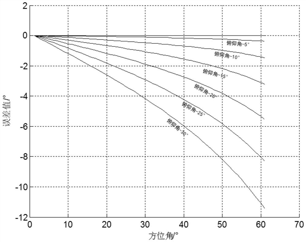
[0057] For example, an electronic reconnaissance aircraft is equipped with a horizontal one-dimensional interferometer direction-finding array at a flight altitude of 10,000m to perform direction-finding positioning on a sea surface electronic radiation source target 50km away in a 45° direction. The arrival angle of the signal measured by the interferometer is 43.90°, and the target distance is estimated to be about 50km. According to the digital map of the area, the target altitude is about 0m, and the calculated height / distance difference ratio is 0.2. Look up Table 2, and the corrected value is 1.13 according to the linear interpolation method , the azimuth is corrected, and the final output azimuth is 45.03°, and the measurement error is reduced from 1.1° to 0.03°.


PUM


Abstract

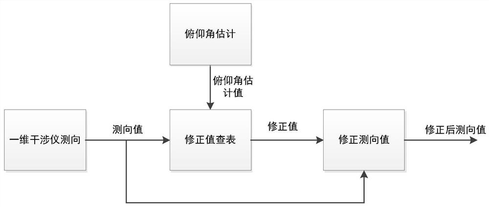
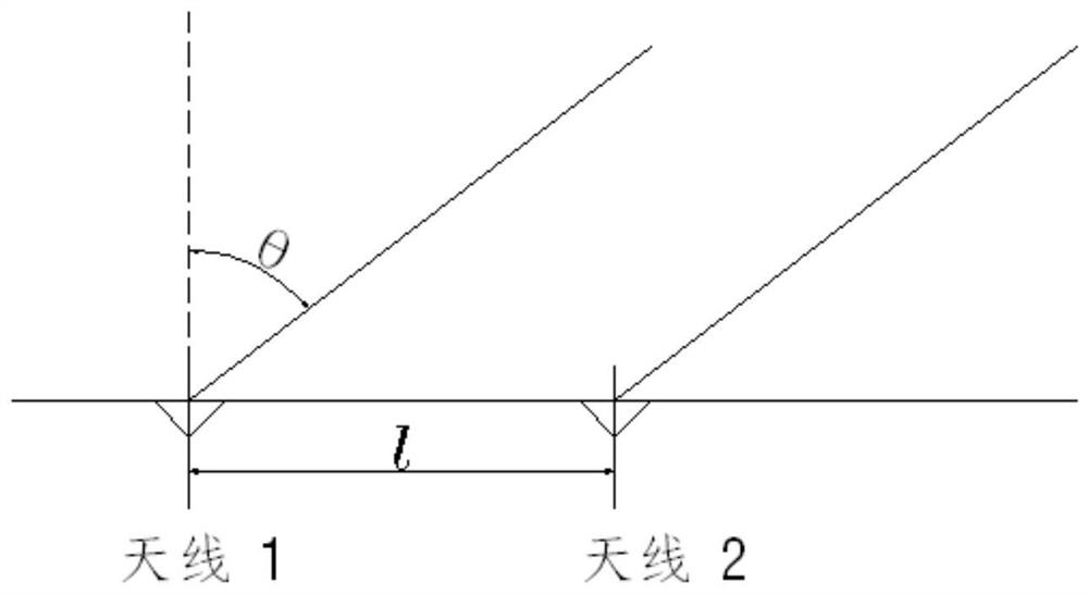
The invention discloses a method for correcting the direction-finding coning effect of a one-dimensional interferometer, based on the direction-finding principle of the one-dimensional interferometer, a signal arrival angle theta is shown in the specification, phi is the phase difference of two paths of signals, lambda is the signal wavelength, l is the antenna spacing, and when an incident signal and an antenna visual axis are not in the same plane, the coning effect exists. The correction method comprises the following steps: based on an obtained signal pitch angle beta and a measured signal arrival angle theta, completing correction calculation of an azimuth angle alpha through the following formula: alpha = sin-1 (sin theta/cos beta). According to the method, the influence of a coning effect caused by a large pitch angle can be avoided, and the azimuth direction finding precision of the one-dimensional interferometer can be improved.

Description

technical field [0001] The invention belongs to the field of electronic technology, in particular to a method for correcting the direction-finding cone effect of a one-dimensional interferometer. Background technique [0002] In the field of electronic reconnaissance, interferometer direction finding is a relatively mature direction finding system, which can take into account the size of the antenna array and the accuracy of direction finding. With the development of technology, the intermediate frequency digital interferometer measurement technology produced by the combination of direction finding technology and digital technology has the advantages of high sensitivity, high direction finding accuracy, good stability, and the ability to use phase change rate to achieve high precision and fast positioning, and can Adapt to complex electromagnetic signal environment, widely used. However, it is also limited by the installed platform and hardware resources. Generally, only on...

Claims


Application Information

Patent Timeline
Patent Type & Authority Applications(China)
IPC IPC(8): G01S3/14G01S3/02
CPCG01S3/14G01S3/023
Inventor 刘永清陈长泳何文波袁泉范立
Owner SOUTHWEST CHINA RES INST OF ELECTRONICS EQUIP
Why Eureka
Try Eureka