Multi-laser radar external parameter calibration method, device and equipment and storage medium

A laser radar and multi-laser technology, applied in image data processing, complex mathematical operations, instruments, etc., can solve problems such as offset, low calibration efficiency, and low precision, and achieve simple calibration operations, reduce calibration costs, and improve efficiency. Effect

Pending Publication Date: 2022-01-04
SHANGHAI ZHENHUA HEAVY IND
View PDF0 Cites 6 Cited by
  • Summary
  • Abstract
  • Description
  • Claims
  • Application Information

AI Technical Summary

Problems solved by technology

But this also leads to a new problem: due to the different positions of each laser radar device, there will be a certain degree of offset between the environmental data collected by each laser radar device
Among them, traditional manual calibration uses manual measurement or instrument measurement to measure the transformation relationship between the lidar coordinate system and the reference coordinate system. Although this method is simple in principle, it requires high precision of the operator's operation and the accuracy of the measuring instrument. , so its generalizability is not high, and the calibration accuracy is unstable and will vary with the level of the operator
The calibration object measurement method determines the external parameters of the laser radar device by matching a specific calibration object. This method also has certain drawbacks. Since the laser radar has different reflectivity for objects of different colors and materials, the search for control points has certain limitations. At the same time, the process of moving the control point requires a lot of human participation, and the calibration accuracy also depends on the parameters between other sensors and the control point, so this calibration method has low calibration efficiency and low accuracy.

Method used


Image

  • Multi-laser radar external parameter calibration method, device and equipment and storage medium
  • Multi-laser radar external parameter calibration method, device and equipment and storage medium
  • Multi-laser radar external parameter calibration method, device and equipment and storage medium

Examples


Embodiment Construction

[0056] In order to enable those skilled in the art to better understand the solutions of the present invention, the following will clearly and completely describe the technical solutions in the embodiments of the present invention in conjunction with the drawings in the embodiments of the present invention. Obviously, the described embodiments are only It is a part of embodiments of the present invention, but not all embodiments. Based on the embodiments of the present invention, all other embodiments obtained by persons of ordinary skill in the art without making creative efforts belong to the protection scope of the present invention.

[0057] It should be noted that the terms "first" and "second" in the description and claims of the present invention and the above drawings are used to distinguish similar objects, but not necessarily used to describe a specific sequence or sequence. It is to be understood that the data so used are interchangeable under appropriate circumstan...


PUM


Abstract

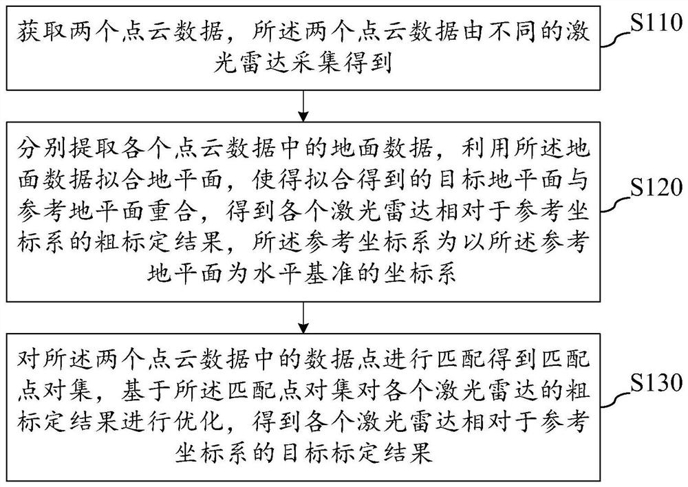
The invention provides a multi-laser radar external parameter calibration method, device and equipment and a storage medium, and the method comprises the steps of: acquiring two pieces of point cloud data which are collected by different laser radars; extracting ground data from the point cloud data respectively, fitting a ground plane by utilizing the ground data, coinciding a target ground plane obtained through fitting with a reference ground plane to obtain a rough calibration result of the laser radars relative to a reference coordinate system, wherein the reference coordinate system is a coordinate system with the reference ground plane as a horizontal datum; and matching data points in the two pieces of point cloud data to obtain a matching point pair set, and optimizing the rough calibration result of each laser radar based on the matching point pair set to obtain a target calibration result of each laser radar relative to the reference coordinate system. According to the multi-laser radar external parameter calibration method, the calibration operation is simple, and the precision and efficiency of laser radar external parameter calibration can be improved.

Description

technical field [0001] The present invention relates to the technical field of laser radar, in particular to a multi-laser radar external parameter calibration method, device, equipment and storage medium. Background technique [0002] In recent years, with the rapid development of intelligent driving technology, lidar has the characteristics of high precision, large ranging range, and is not affected by light. It is widely used in the environment of obstacle detection, real-time positioning and map construction of intelligent driving vehicles. perception field. [0003] In order to enhance the perception of the surrounding environment, considering the scanning range and field of view of the lidar, multiple lidar devices will be configured on a smart driving car. But this also leads to a new problem: due to the different positions of each laser radar device, there will be a certain degree of offset between the environmental data collected by each laser radar device. Theref...

Claims


Application Information

Patent Timeline
Patent Type & Authority Applications(China)
IPC IPC(8): G06T7/80G06K9/62G06F17/16G06F17/11
CPCG06T7/80G06F17/16G06F17/11G06T2207/10044G06F18/22
Inventor 欧阳乐王全宇刘春明黄旭东常奇吴一稷张越王怀志
Owner SHANGHAI ZHENHUA HEAVY IND
Why Eureka
Try Eureka