
Wafer level chip packaging structure and packaging method

A wafer-level chip and packaging structure technology, applied in the direction of assembling microstructure devices, microstructure devices, manufacturing microstructure devices, etc., can solve the problems of complex packaging process, large package size and high thickness, and achieve simple process and package size Small and thin effect

Pending Publication Date: 2022-01-04
江苏中科智芯集成科技有限公司
View PDF0 Cites 0 Cited by
  • Summary
  • Abstract
  • Description
  • Claims
  • Application Information

AI Technical Summary

Problems solved by technology

[0006] Therefore, the technical problem to be solved by the present invention is to overcome the need to form a chip with a cavity structure on the functional surface in the prior art. The packaging process of the prior art is relatively complicated, the package size is large, the thickness is also high, and the airtightness is not enough. To solve the problem of certain risks, a wafer-level chip packaging structure and packaging method are provided.

Method used


Image

  • Wafer level chip packaging structure and packaging method
  • Wafer level chip packaging structure and packaging method
  • Wafer level chip packaging structure and packaging method

Examples


Embodiment Construction

[0046] The technical solutions of the present invention will be clearly and completely described below in conjunction with the accompanying drawings. Apparently, the described embodiments are some of the embodiments of the present invention, but not all of them. Based on the embodiments of the present invention, all other embodiments obtained by persons of ordinary skill in the art without making creative efforts belong to the protection scope of the present invention.

[0047]In the description of the present invention, it should be noted that the terms "center", "upper", "lower", "left", "right", "vertical", "horizontal", "inner", "outer" etc. The indicated orientation or positional relationship is based on the orientation or positional relationship shown in the drawings, and is only for the convenience of describing the present invention and simplifying the description, rather than indicating or implying that the referred device or element must have a specific orientation, o...


PUM


Abstract

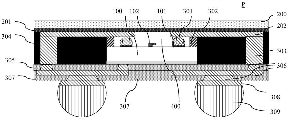
The invention discloses a wafer level chip packaging structure and a corresponding packaging method. The wafer level chip packaging structure comprises a substrate and a chip, wherein the chip is inversely mounted on the surface of the substrate, and a closed cavity is formed between the functional surface of the chip and the substrate. According to the invention, the packaging structure can be formed on one substrate, the process is simple, the packaging size can be effectively reduced, the thickness can be reduced, and the air tightness of the whole structure can be effectively guaranteed.

Description

technical field [0001] The invention relates to the field of chip technology, in particular to a wafer-level chip packaging structure and packaging method. Background technique [0002] For the packaging process that needs to form a cavity structure on the surface, such as MEMS chips and filter chips, etc., the surface needs to be packaged without contact. The existing technology is more representative in the following two ways: [0003] 1. First make the bottom part containing the chip and the cover part with reserved space, and then fasten the cover part to the bottom part containing the chip by bonding, and pass the cover reserved near the chip The space forms a cavity. In this method, the upper and lower parts need to be designed together, the size is the same, and the cost is relatively high. [0004] 2. The chip is pasted on the substrate, and the front side of the chip is exposed through a hole in the substrate, and then the substrate with the chip mounted on it is ...

Claims


Application Information

Patent Timeline
IPC IPC(8): H01L23/48H01L21/60B81B7/00B81B7/02B81C1/00
CPCH01L23/48H01L24/81B81B7/007B81B7/02B81C1/00261H01L2224/81B81C2203/0118
Inventor 陈峰姚大平
Owner 江苏中科智芯集成科技有限公司
Learn More