Communication antenna mast with height convenient to adjust

A technology for adjusting height and communication antenna. It is applied in the direction of antenna, antenna parts, antenna support/installation device, etc. It can solve the problems of inability to adjust height change, increase the difficulty of installation steps, and height error of utility poles, so as to facilitate manual transportation. , the effect of increasing usability and reducing the load

Inactive Publication Date: 2022-01-04
XIAN RUILIN ELECTRONICS TECH CO LTD
View PDF0 Cites 0 Cited by
  • Summary
  • Abstract
  • Description
  • Claims
  • Application Information

AI Technical Summary

Problems solved by technology

[0005] The purpose of the present invention is to provide a communication antenna mast that can be easily adjusted in height to solve the above-mentioned background technology. Because the height of the electric pole is mainly determined by the voltage level, the higher the voltage level, the higher the electric pole, while the existing Most of the communication antenna poles are made of reinforced concrete, and their height cannot be adjusted. Therefore, it is necessary to use a variety of poles with different heights, which increases the difficulty of the installation steps, and during installation, due to the different depths of the foundation, it will make the poles There is a certain error in the height, which leads to unstable circuit transmission

Method used


Image

  • Communication antenna mast with height convenient to adjust
  • Communication antenna mast with height convenient to adjust
  • Communication antenna mast with height convenient to adjust

Examples


Embodiment Construction

[0025] The following will clearly and completely describe the technical solutions in the embodiments of the present invention with reference to the accompanying drawings in the embodiments of the present invention. Obviously, the described embodiments are only some of the embodiments of the present invention, not all of them. Based on the embodiments of the present invention, all other embodiments obtained by persons of ordinary skill in the art without creative efforts fall within the protection scope of the present invention.

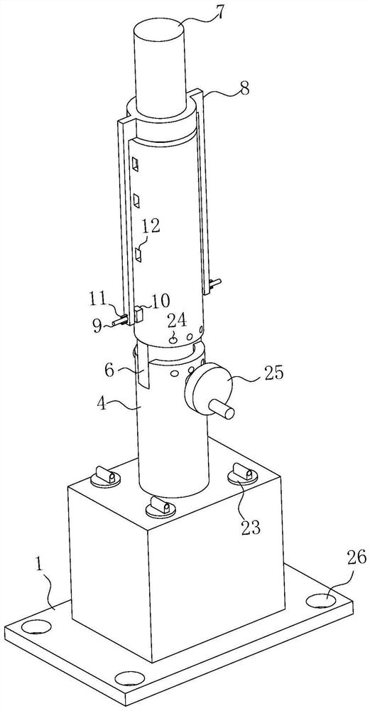
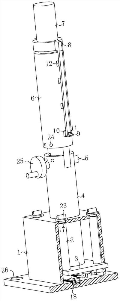
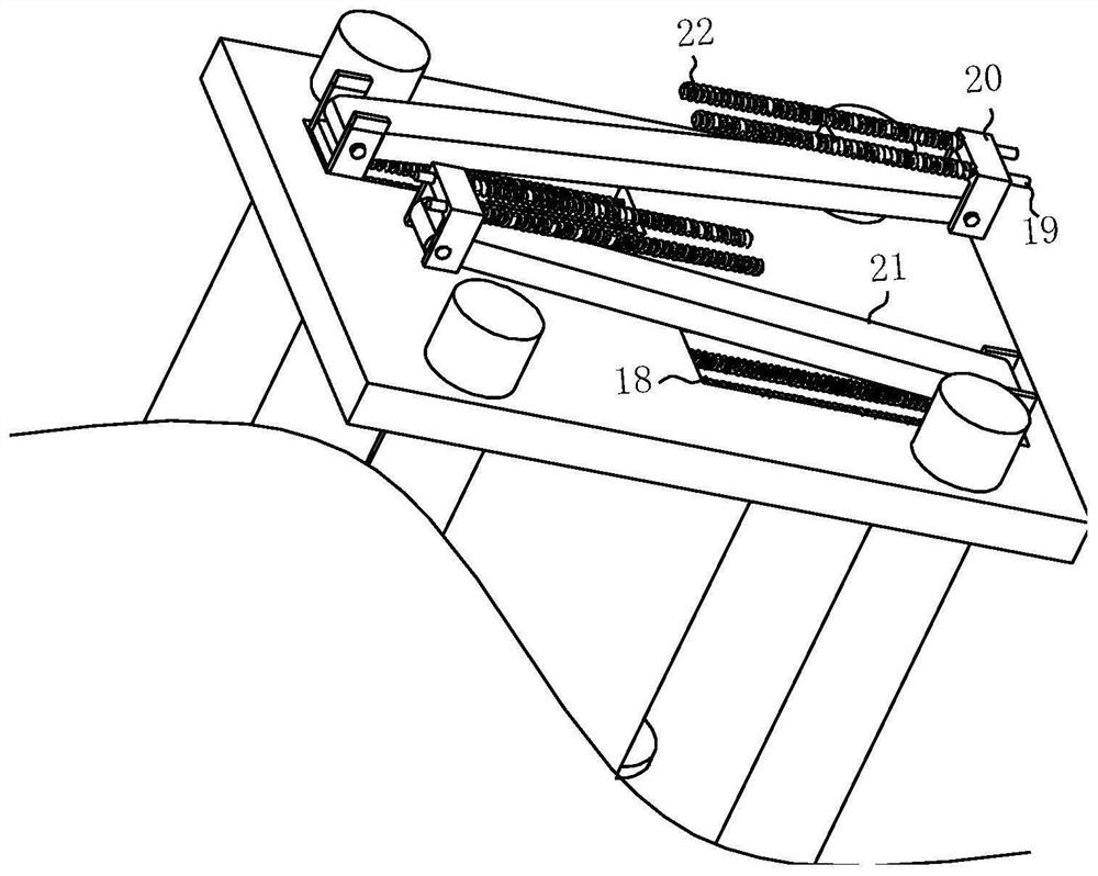
[0026] see Figure 1-4 , the present invention provides a technical solution: a communication antenna mast that is convenient for height adjustment, including a T-shaped base 1, the T-shaped base 1 is a hollow structure, and the bottom of the T-shaped base 1 is rotatably connected to several antennas distributed in an array. Hollow threaded rod 2, the surfaces of several hollow threaded rods 2 are jointly threaded to be connected with slide plate 3, a...


PUM


Abstract

The invention discloses a communication antenna mast with height convenient to adjust in the field of communication instruments, which comprises a T-shaped base, the T-shaped base is of a hollow structure, the bottom end of the T-shaped base is rotatably connected with a plurality of hollow threaded rods distributed in an array, the surfaces of the plurality of hollow threaded rods are jointly in threaded connection with a sliding plate, the top end of the sliding plate is fixedly connected with a first-stage antenna mast, the top end of the first-stage antenna mast penetrates through the top end of the T-shaped base and then is slidably connected with the top end of the T-shaped base, the top end of the first-stage antenna mast is rotatably connected with a rotating rod, the surface of the rotating rod is fixedly connected with a second-stage antenna mast, and the surface of the second-stage antenna mast is provided with an extending mechanism. And an adjusting mechanism is arranged in the hollow threaded rod. By adopting a mode of folding and rotating connection of the first-stage antenna rod and the second-stage antenna rod, the use space of the antenna rod is reduced, manual transportation is facilitated, the antenna mast can be precisely adjusted to the required height through the common adjustment effect of the extension mechanism and the adjustment mechanism, the operation is simple, the antenna mast can be suitable for various different voltages, and the usability of the antenna mast is improved.

Description

technical field [0001] The invention discloses a communication antenna rod which is convenient for height adjustment in the field of communication equipment. Background technique [0002] The antenna tower refers to the tower structure used to support and suspend the antenna. The pole-tower structure is a general term for tower structures and pole structures. The tower structure is a towering structure with a fixed lower end and a free upper end; the rod structure is composed of a vertical slender mast whose lower end is hinged or rigidly connected and several layers of stay wires separated by a certain height along the shaft. The lower end of the stay wire is anchored to the ground. The guy wire keeps the shaft upright and stable. [0003] In the prior art, since the height of the utility pole is mainly determined by the voltage level, the higher the voltage level, the higher the pole, while the existing communication antenna poles are mostly made of reinforced concrete, ...

Claims


Application Information

Patent Timeline
Patent Type & Authority Applications(China)
IPC IPC(8): H01Q1/12H01Q1/20H01Q3/04
CPCH01Q1/1235H01Q1/20H01Q3/04
Inventor 袁惠清李云策
Owner XIAN RUILIN ELECTRONICS TECH CO LTD
Why Eureka
Try Eureka