
Four-phase switched reluctance generator converter and control method thereof

A reluctance generator and converter technology, applied in the direction of controlling generators, controlling generators, and control systems through magnetic field changes, can solve the problem of increasing the structure and control complexity of converters, reducing the advantages of switched reluctance motors, Increase the cost of the converter and other issues to achieve the effect of reducing volume and weight, reducing switching loss, and improving adaptability

Pending Publication Date: 2022-01-04
CHINA JILIANG UNIV
View PDF0 Cites 0 Cited by
  • Summary
  • Abstract
  • Description
  • Claims
  • Application Information

AI Technical Summary

Problems solved by technology

[0004] Among the current switched reluctance generator converters, the research on the converter system based on variable excitation voltage has begun to rise. However, in many kinds of variable excitation converters, either an isolation link is required or a large amount of power is required. The electronically controllable switching tube either sacrifices diversified functions or reduces its adaptability, which increases the complexity of the structure and control of the converter, increases the cost of the converter, reduces the advantages brought by the switched reluctance motor itself, and reduces Therefore, following the advantages of the switched reluctance motor body, the development of a converter with a simple structure and satisfying variable excitation is bound to be one of the trends in its application.

Method used


Image

  • Four-phase switched reluctance generator converter and control method thereof

Examples


Embodiment Construction

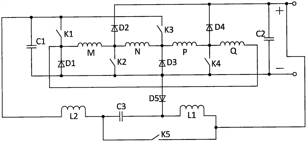
[0018] A four-phase switched reluctance generator converter and its control method in this embodiment, the circuit structure of the converter is as follows figure 1 As shown, it consists of the first capacitor C1, the second capacitor C2, the third capacitor C3, the first switching tube K1, the second switching tube K2, the third switching tube K3, the fourth switching tube K4, the fifth switching tube K5, The first diode D1, the second diode D2, the third diode D3, the fourth diode D4, the fifth diode D5, the first inductor L1, the second inductor L2, the first phase winding M , the second phase winding N, the third phase winding P, and the fourth phase winding Q, one end of the first capacitor C1 is connected to the anode of the first switching tube K1, the anode of the third switching tube K3, and one end of the second inductor L2, the first The other end of the capacitor C1 is connected to the anode of the first diode D1, the cathode of the second switch tube K2, the anode...


PUM


Abstract

The invention relates to a four-phase switched reluctance generator converter and a control method thereof, the converter of the invention is composed of three capacitors, five switch tubes, five diodes, two inductors and four-phase windings connected to a switched reluctance generator; and the excitation voltage value shared by the windings can be controlled through a PWM switch of a fifth switch tube, the other four switch tubes aim at excitation and power generation control of each phase winding, the converter has no isolation link, excitation voltage and power generation voltage are decoupled, the quantity of the main switch tubes is only one more than that of the phase windings, the structure and control are simple, and the reliability is high. The invention is suitable for being applied to the field of switched reluctance generator systems with even number of phase windings driven by various kinds of power.

Description

technical field [0001] The invention relates to the field of switched reluctance motor systems, in particular to a switched reluctance generator converter with a self-excited variable excitation voltage decoupled from a power generation voltage, no isolation link, and a minimum number of switch tubes and its control method. Background technique [0002] The structure of the switched reluctance motor is extremely simple and strong. The main reason is that there is no winding or permanent magnet on the rotor. It is low in cost, high temperature and high speed, and should have a wide range of application prospects. [0003] At present, the switched reluctance motor is very rare to be used as a generator. During its operation, the phase windings to be energized must be selected according to the relative positional relationship between the salient poles of the stator and rotor. , the interior of each phase winding is subdivided into two stages of excitation and power generation,...

Claims


Application Information

Patent Timeline
IPC IPC(8): H02P9/30H02P9/38
CPCH02P9/305H02P9/38
Inventor 孙冠群卢子萌张宇
Owner CHINA JILIANG UNIV
Learn More