Ball screw mechanism and linear motion device

A ball screw and ball technology, used in transmissions, mechanical equipment, belts/chains/gears, etc., can solve the problems of complex structure, hindering the smooth return of balls, and difficulty in restraining

A ball screw and ball technology, used in transmissions, mechanical equipment, belts/chains/gears, etc., can solve the problems of complex structure, hindering the smooth return of balls, and difficulty in restraining

CN113892003APending Publication Date: 2022-01-04水野逸人

Image

  • Ball screw mechanism and linear motion device
  • Ball screw mechanism and linear motion device
  • Ball screw mechanism and linear motion device

Examples


Embodiment Construction

[0055] Hereinafter, embodiments of the present invention will be described in detail with reference to the drawings.

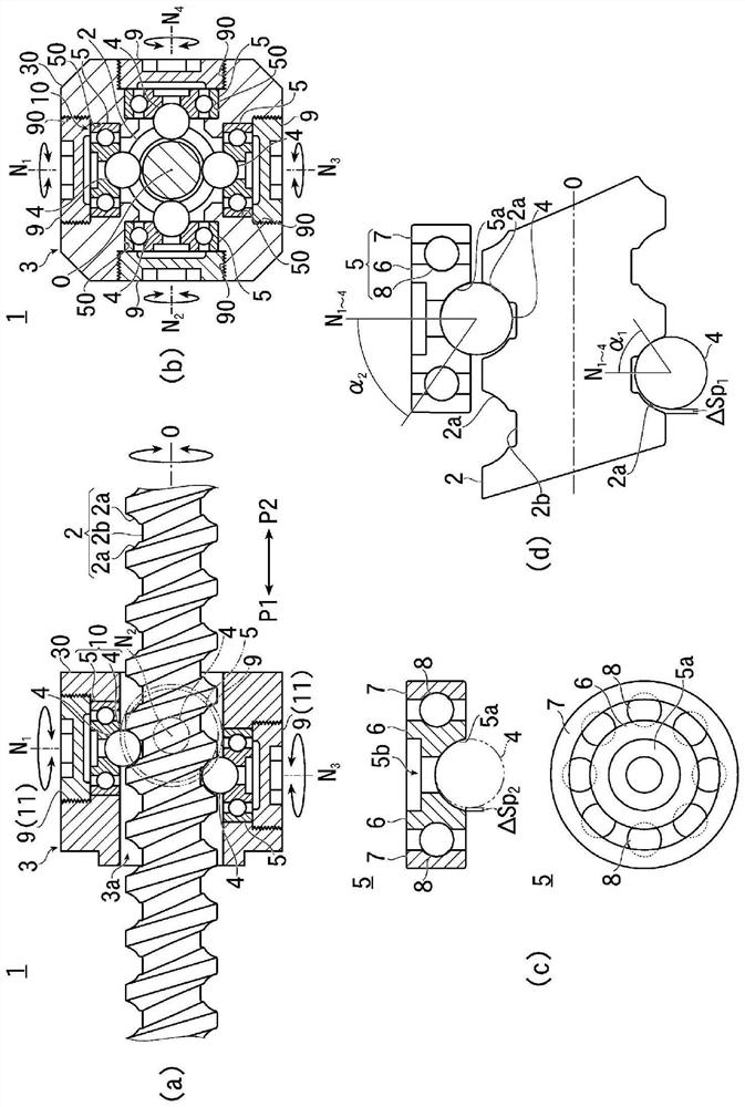
[0056] figure 1 (a) to figure 1 (d) in shows an embodiment of the ball screw according to the present invention, figure 1 (a) is a front partial sectional view showing the overall structure, figure 1 (b) is a side view partial sectional view showing the overall structure, figure 1 (c) is a front partial sectional view and a top view showing the structure of the ball bearing, figure 1 (d) is an explanatory diagram showing the dimensional relationship between the screw shaft and the balls.

[0057] Such as figure 1 As shown in (a), the ball screw mechanism 1 of this embodiment has: a screw shaft 2 extending linearly; a moving body 3 provided around the screw shaft 2; The thrust force of the screw shaft 2 is transmitted to the moving body 3 to move the moving body 3 along the screw shaft 2 .

[0058] The screw shaft 2 of the present embodiment has a solid ...


PUM


Abstract

Provided is a ball screw mechanism that can prevent vibration and noise and avoid an increase in heat by ensuring smooth movements of balls without the occurrence of obstructions or the like of the balls on a screw shaft, and without the need to consider the return of the balls as in a conventional circulation-type ball screw. The present invention is provided with a screw shaft 2 that has a spiral groove 2a and extends linearly; a housing 30 that surrounds the circumference of the screw shaft 2; and a plurality of balls 4 and ball bearings 5 that transmit the thrust of the screw shaft 2 to the housing 30. The ball bearings 5 each have outer rings 7 that are attached and fixed to the housing 30 at predetermined intervals along the spiral groove 2a of the screw shaft 2, and inner rings 6 provided with a concave spherical contact surface 5a, which is in contact with the balls 4, on the side surface facing the screw shaft 2. The inner rings 6 are installed so as to be rotatable about rotation axes N1-N4 that cross the rotation axis O of the screw shaft 2. The balls 4 are disposed adjacent to the inside of the spiral groove 2a of the screw shaft 2 at predetermined intervals while in contact with the contact surfaces 5a of the ball bearings 5.

Description

technical field [0001] The present invention relates to the technology of a ball screw mechanism using a screw shaft and balls. Background technique [0002] Conventionally, as the ball screw, various ball screws are known. [0003] For example, there are non-recirculating ball screws and recirculating ball screws in which balls are fixed to sliding bearings provided in the nut and the balls are rotated on the screw shaft in the non-recirculating ball screw. While moving the nut, in the recirculating ball screw, in the ball nut located on the ball screw shaft, a plurality of balls are wound around the screw shaft 1.5 to 3.5 times, and the balls sent to the nut discharge port are passed through the tube Or guides such as return grooves return to the original nut entry, allowing the balls to circulate within the nut. [0004] However, conventional recirculating ball screws have various problems as described below, which cannot be solved at present. [0005] For example, whe...

Claims


Application Information

Patent Timeline
04 Jan 2022
Publication
CN113892003A
IPC
F16H25/22
CPC
F16H25/2261; F16H25/2233
Inventors
水野逸人