Low-temperature rotary blending box

A mixing and low-temperature technology, applied in mixers, shaking/oscillating/vibrating mixers, dissolving, etc., can solve the problems of high experimental cost, high price, and high purchase cost, and achieve low experimental cost, fast experimental efficiency, and convenience. popular effect

Inactive Publication Date: 2022-01-07
耿珊
View PDF0 Cites 2 Cited by
  • Summary
  • Abstract
  • Description
  • Claims
  • Application Information

AI Technical Summary

Problems solved by technology

[0004] Among them, in step (2), in order to ensure that the protein is fully bound, it can be slowly shaken for a longer time or even overnight according to the needs of the schedule. In the experiment, a shaker is often used to shake the target protein solution. However, the existing Most of the shaking tables in the market only shake the target protein solution in one direction (left and right). The target protein solution is only subjected to force in one direction and the shaking is uneven. The shaker that can shake the target protein solution at 360° has a high cost and the purpose The protein solution needs to be shaken at 4°C. Most

Method used


Image

  • Low-temperature rotary blending box
  • Low-temperature rotary blending box
  • Low-temperature rotary blending box

Examples


Embodiment 1

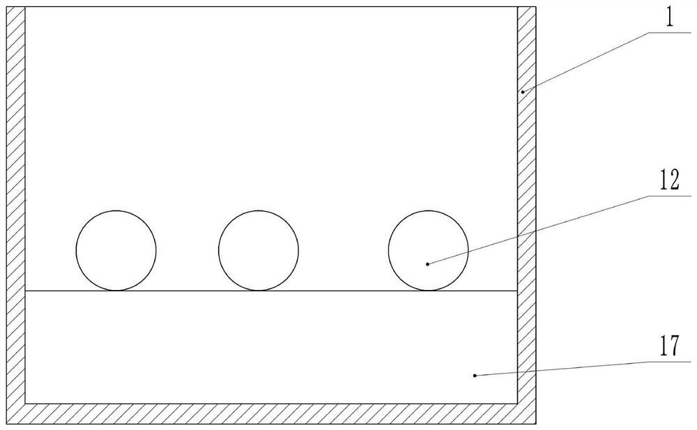
[0031] as attached figure 1 Shown:

[0032] The insulation box body 1 is provided with an opening, and the sphere 12 includes a detachable upper sphere 12 and a lower sphere 12 to ensure that the standard EP tube containing the target protein solution can be installed inside the sphere 12, and the inside of the sphere 12 is hollow to ensure that the test tube can Put it into the inside of the sphere 12, the sphere 12 is set inside the insulation box body 1, after the standard EP tube is put in, the upper and lower spheres 12 are closed, the inside of the insulation box body 1 is provided with an ice box 17, and the inside of the ice box 17 is provided with ice, The ice box 17 is located at the bottom of the heat preservation box body 1, and its volume accounts for about 1 / 3rd of the heat preservation box body 1. Put the ice box 17 with ice inside the heat preservation box body 1, place the sphere 12 equipped with standard EP tubes on the top of the ice box 17 through the open...

Embodiment 2

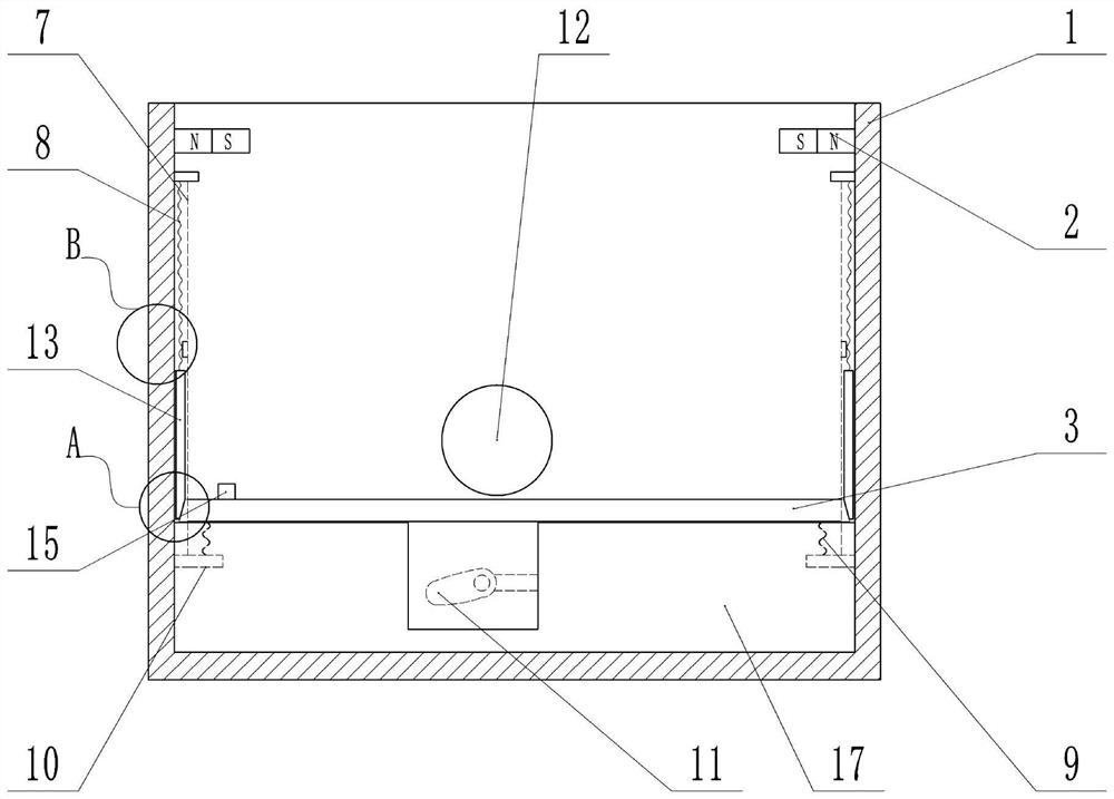
[0035] as attached figure 2 , attached image 3 , attached Figure 4 , attached Figure 5 , attached Image 6 And attached Figure 7 Shown:

[0036] The difference from Example 1 is that the material of the sphere 12 is iron, the upper sphere 12 is provided with buckles, and the lower sphere 12 is provided with a slot, and the standard EP tube containing the target protein solution is placed inside the sphere 12 , close the buckle and the slot, so that the ball 12 is closed. The top wall inside the upper sphere 12 is provided with a fixedly connected first cylinder 21, the first cylinder 21 is welded on the top wall inside the upper sphere 12, the inside of the first cylinder 21 is provided with a third piston 22 that is slidingly connected, and the third piston 22 and the top wall of the first cylinder 21 are provided with a fourth spring 23 to ensure that the third piston 22 will not fall off arbitrarily due to gravity, and the bottom wall inside the lower sphere 12 i...

Embodiment 3

[0047] as attached Figure 8 Shown:

[0048] Different from Embodiments 1 and 2, the second cylinder 24 is provided with two fifth pistons 28 that are slidingly connected, and a sixth spring 27 is provided between the fifth piston 28 and the side wall of the second cylinder 24. The five pistons 28 and the fourth piston 25 form a closed space, the fifth piston 28 is provided with a fixed rod 29 that is fixedly connected, the fixed rod 29 is welded on the surface of the fifth piston 28, and the two fixed rods 29 are arranged correspondingly. The lower end of the EP tube is inserted into the second cylinder 24 on the lower ball 12, the fourth piston 25 slides downward under force, the fifth spring 26 is squeezed, and at the same time, the fifth piston 28 moves toward the standard EP tube. The six springs 27 are compressed, and the two fixed rods 29 on the fifth piston 28 clamp both sides of the standard EP tube, so that the standard EP tube can be fixed better. In order to ensur...


PUM


Abstract

The invention belongs to the technical field of biology, and particularly discloses a low-temperature rotary blending box which comprises a heat preservation box body and a ball body. The ball body comprises an upper ball body and a lower ball body which are detachable; an opening is formed in the upper portion of the heat preservation box body, a fixedly-installed ice box is arranged in the heat preservation box body, and ice is arranged in the ice box. After a standard EP tube is inserted into the ball body, the heat preservation box body is placed on a shaking table, the ball body continuously rolls along with shaking of the shaking table, and a target protein solution of the standard EP tube in the ball body is continuously shaken, so that the target protein solution is uniformly mixed. According to the scheme, a target protein solution in a standard EP tube can be uniformly shaken, and the experiment cost is relatively low.

Description

technical field [0001] The invention relates to the field of biotechnology, in particular to a low-temperature rotary mixing box. Background technique [0002] Co-immunoprecipitation (Co-Immunoprecipitation) is a classic method for studying protein interaction based on the specific interaction between antibody and antigen, and is an effective method to determine the physiological interaction of two proteins in intact cells. It is a method developed by utilizing the specific binding of antigen and antibody and the phenomenon that protein A or G of bacteria specifically binds to the Fc fragment of immunoglobulin. The basic principle is to add an antibody against the protein of interest to the cell lysate, and then add Protein A or G that binds to the Agarose beads that specifically binds to the antibody after incubation. If there is a target protein that binds to the protein of interest in the cell, then Such a complex can be formed: "Protein of interest-antibody protein anti...

Claims


Application Information

Patent Timeline
IPC IPC(8): B01F31/20B01F35/92B01F101/23
Inventor 耿珊
Owner 耿珊
Why Eureka
Try Eureka