Lifting type permanent magnet stirring device and method

A permanent magnetic stirring and lifting technology, which is applied in the direction of mixer accessories, chemical instruments and methods, transportation and packaging, etc., can solve unfavorable melt solidification, structure and performance, unfavorable regulation and improvement of billet quality, single magnetic field mode, etc. problems, to achieve the effect of improving billet quality, reducing solute segregation, and realizing heat transfer

Active Publication Date: 2022-01-07
CENT SOUTH UNIV
View PDF11 Cites 1 Cited by
  • Summary
  • Abstract
  • Description
  • Claims
  • Application Information

AI Technical Summary

Problems solved by technology

Another example is the patent CN208591780U which discloses a permanent magnetic stirrer which can effectively prevent segregation. The rotation of the propeller-like blades drives the melt to move evenly. The structure is relatively complicated, and only a single magnetic field movement mode can be realized.
In short, the existing permanent magnetic stirring device has a relatively complex structure and a relatively single magnetic field mode, which is not conducive to regulating and improving the quality of the slab, and when used in the field of experimental research, it is not conducive to the diversified research of permanent magnetic stirring in the laboratory. Influence on melt solidification, structure and performance

Method used


Image

  • Lifting type permanent magnet stirring device and method
  • Lifting type permanent magnet stirring device and method

Examples


Embodiment 1

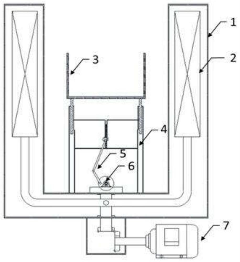
[0037] Put the MgO crucible containing the sulfur-containing non-quenched and tempered steel melt on the tray, turn on the permanent magnetic stirring device, apply alternating permanent magnetic stirring to the melt, first rotate forward for 1 minute and then reverse for 1 minute, and reciprocate in this way. The stirring time is 10 minutes, the magnetic induction intensity is 2000Gs during the stirring process, and the magnet rotation speed is 200rpm. After the stirring was completed, the ingot was taken out and cooled with water to obtain a sample. The analysis and detection of MnS in the sample found that the average equivalent diameter is 3.8 μm, the main shape of MnS is spindle, short rod and ellipse, and there is no aggregation distribution phenomenon.

Embodiment 2

[0039] Put the MgO crucible containing the sulfur-containing non-quenched and tempered steel melt on the tray, turn on the permanent magnetic stirring device, apply alternating permanent magnetic stirring to the melt, first rotate forward for 2 minutes and then reverse for 2 minutes, and reciprocate in this way. The stirring time is 12min, the magnetic induction intensity is 1500Gs during the stirring process, and the magnet rotation speed is 150rpm. After the stirring was completed, the ingot was taken out and cooled with water to obtain a sample. The analysis and detection of MnS in the sample found that the average equivalent diameter is 4.2 μm, the main shape of MnS is spindle, short rod and ellipse, and there is no aggregation distribution phenomenon.

[0040] To sum up, the device and method of this application can easily realize multi-level and diversified control of the magnetic field at the position of the melt, such as magnetic field strength, magnetic field movement...


PUM


Abstract

The invention discloses a lifting type permanent magnet stirring device and a method. The device comprises a sleeve, a permanent magnet, a permanent magnet driving mechanism, a tray, a telescopic rod and a telescopic rod driving mechanism, the sleeve and the permanent magnet are assembled in a nested mode, the permanent magnet is driven by the permanent magnet driving mechanism to rotate, and the tray is arranged in the sleeve in a supported mode through the telescopic rod; the telescopic rod is driven by the telescopic rod driving mechanism to ascend and descend. The permanent magnet stirring device has the advantages of being simple in structure, easy and convenient to maintain, low in cost, convenient to operate and diversified in magnetic field mode, the controllability of the casting blank quality is improved, and the casting blank quality is improved. The device can be widely applied to the field of metallurgical melt permanent magnet stirring and the field of experimental research, meets the requirement for diversified research on the influence of permanent magnet stirring on melt solidification, tissue, performance and the like in a laboratory, and lays a foundation for subsequent industrial application.

Description

technical field [0001] The invention relates to the technical field of metallurgical melt stirring, in particular to a lifting type permanent magnetic stirring device and method. Background technique [0002] At this stage, the three-phase AC electromagnetic stirrer has become a mainstream, effective and standard continuous casting configuration that can control the quality of the slab. More and more metallurgists are paying attention to regulating the quality of slab by applying electromagnetic stirring to the melt. [0003] However, electromagnetic stirring requires high-power variable-frequency current to generate an alternating magnetic field, which faces a series of problems such as complex equipment, high energy consumption, and high maintenance costs. In addition, the stirrer must be cooled by flowing water with a certain pressure, and although high-quality cooling water is used, the service life of the coil is still relatively short. [0004] With the rapid develop...

Claims


Application Information

Patent Timeline
Patent Type & Authority Applications(China)
IPC IPC(8): B01F33/453B01F35/30B01F35/222
Inventor 曾杰王万林彭健飞吴厚发李人升
Owner CENT SOUTH UNIV
Why Eureka
Try Eureka