Aluminum bar casting cooling equipment

A technology of cooling equipment and aluminum rods, which is applied in casting equipment, metal processing equipment, casting molten material containers, etc., can solve the problems of low cooling efficiency, achieve the effects of fast flow speed, convenient water outlet temperature, and reduced resistance

Pending Publication Date: 2022-01-07
王晓虎
View PDF0 Cites 2 Cited by
  • Summary
  • Abstract
  • Description
  • Claims
  • Application Information

AI Technical Summary

Problems solved by technology

[0004] Aiming at the deficiencies of the prior art, the present invention provides an aluminum rod melting and casting cooling equipment, which solves the problem that when the hot water in the current melting and casting system enters the interior of the refrigerator for cooling, only the cold air that is farther away from the hot water exchanges heat with the hot water. , the distant cold air is discharged together with the gas after heat exchange, resulting in the problem of low cooling efficiency

Method used


Image

  • Aluminum bar casting cooling equipment
  • Aluminum bar casting cooling equipment
  • Aluminum bar casting cooling equipment

Examples


Embodiment 1

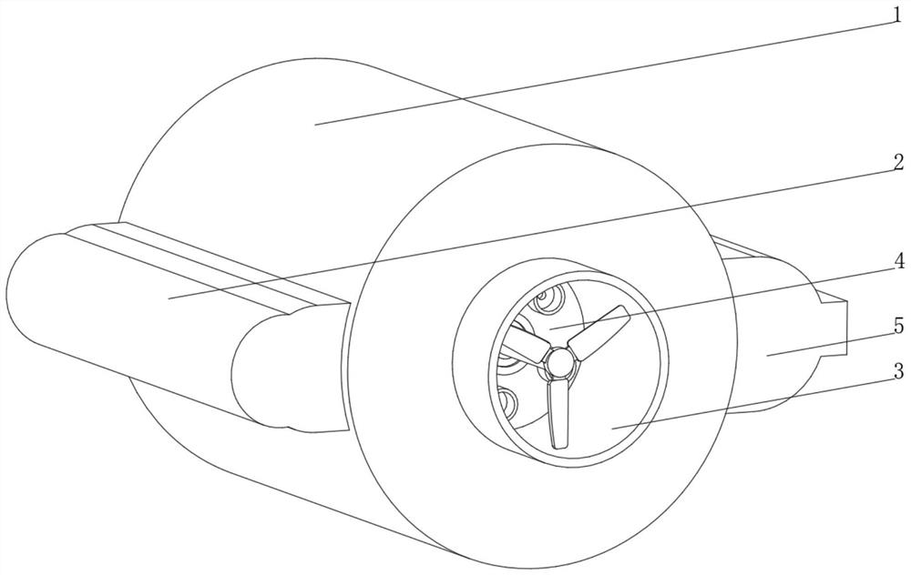
[0034] see Figure 1-3 , the present invention provides a technical solution: an aluminum rod melting and casting cooling equipment, specifically comprising:

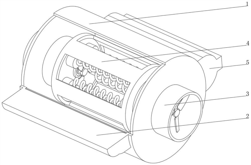
[0035] A fixed outer cylinder 1, one side of the fixed outer cylinder 1 is fixedly connected with a cooling fan 2, and both ends of the fixed outer cylinder 1 are penetrated and communicated with a water delivery pipe 3

[0036] Cooling device 4, the cooling device 4 is arranged inside the fixed outer cylinder 1, and both ends of the cooling device 4 communicate with the water delivery pipe 3;

[0037] An air outlet device 5, the air outlet device 5 is arranged on one side of the fixed outer cylinder 1, and the air outlet device 5 communicates with the fixed outer cylinder 1 side;

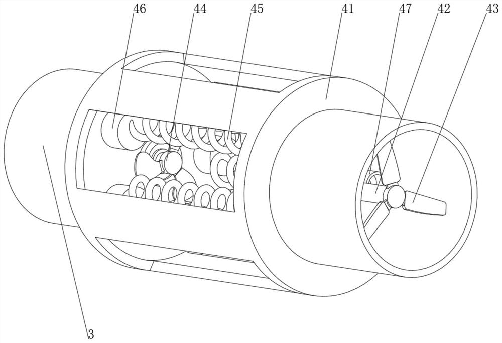
[0038] Cooling device 4 comprises:

[0039] Cooling cylinder 41, the side of the cooling cylinder 41 is provided with air holes, the two ends of the cooling cylinder 41 are connected to the connecting shaft 42 through bearing rotation, and...

Embodiment 2

[0043] see Figure 1-4 On the basis of Embodiment 1, the present invention provides a technical solution: the adjusting device 46 includes a threaded sleeve 461, the inner wall of the threaded sleeve 461 is provided with a sealing groove 462, and the inner wall of the sealing groove 462 is connected with a sealing ring 464 through an air bag 463, and the threaded sleeve 461 An adjusting pipe 465 is threadedly connected to the inner wall of the sleeve 461 , the threaded sleeve 461 runs through the cooling cylinder 41 and is fixedly connected with the cooling cylinder 41 , and one end of the adjusting pipe 465 communicates with the spiral pipe 45 .

[0044] An adjustment device 46 is provided, and the adjustment tube 465 is rotated, the adjustment tube 465 moves inside the threaded sleeve 461 and drives the spiral tube 461 to expand and contract, which facilitates changing the bending degree of the spiral tube 461 and changing the circulation distance of hot water inside the cool...

Embodiment 3

[0046] see Figure 1-5 , On the basis of Embodiment 1 and Embodiment 2, the present invention provides a technical solution: the air outlet device 5 includes an air outlet housing 51, the top and bottom of the inner wall of the air outlet housing 51 are fixedly connected with elastic components 52, and the elastic components 52 are far away from the air outlet housing 51 A sealing strip 53 is fixedly connected to one end of the sealing strip 53, and both ends of the sealing strip 53 extend to the inner wall of the air outlet shell 51. One side of the air outlet shell 51 is connected with an air outlet nozzle 54, and one side of the air outlet shell 51 is connected with the fixed outer cylinder 1. The elastic component 52 includes Fixed rod 521 and arc-shaped spring sheet 522, fixed rod 521 is provided with two groups, and arc-shaped spring sheet 522 is provided with several groups and is evenly distributed between two groups of fixed rods 521, and the fixed rod 521 two ends of ...


PUM


Abstract

The invention discloses aluminum bar casting cooling equipment, and relates to the technical field of fusion casting. The aluminum bar casting cooling equipment specifically comprises a fixed outer cylinder, a cooling device and an air outlet device, wherein an air cooler is fixedly connected to one side of the fixed outer cylinder, the two ends of the fixed outer cylinder penetrate through and communicate with a water conveying pipe cooling device, the cooling device is arranged in the fixed outer cylinder, the two ends of the cooling device communicate with a water conveying pipe, the air outlet device is arranged on one side of the fixed outer cylinder, the air outlet device communicates with one side of the fixed outer cylinder, the cooling device comprises a cooling cylinder, air holes are formed in the side face of the cooling cylinder, and the two ends of the cooling cylinder are rotationally connected with connecting shafts through bearings. According to the aluminum bar casting cooling equipment, cold air of all parts can make contact with a spiral pipe as much as possible and conduct heat exchange with hot water in the spiral pipe, the cooling efficiency can be improved conveniently, air circulation is more violent, and dead corners generated in the fixed outer barrel and the cooling barrel are avoided.

Description

technical field [0001] The invention relates to the technical field of melting and casting, in particular to cooling equipment for melting and casting of aluminum rods. Background technique [0002] The melting and casting furnace is specifically a positive pressure vertical centrifugal vacuum induction melting and casting furnace. The melting and casting furnace provides a melting and casting method that is convenient to control the casting process and the process is simplified. It provides a mold with a cavity that conforms to the part to be cast, and performs insulation on the above mold. Use white corundum and silica sol to coat the cavity wall of the mold, set the metal wire or plate or melting nozzle in the mold cavity, and place solid conductive flux in the gap between the metal wire or plate or melting nozzle, now The hot water discharged from some casting furnaces needs to flow back to the cooling tower for cooling, and a refrigerator is used to cool down the hot wa...

Claims


Application Information

Patent Timeline
Patent Type & Authority Applications(China)
IPC IPC(8): B22D41/005
CPCB22D41/005
Inventor 王晓虎
Owner 王晓虎
Why Eureka
Try Eureka