
Embedded starting and rotating device of small turbine engine and aircraft with embedded starting and rotating device

A turbine engine and embedded technology, which is applied in the direction of gas turbine devices, gas turbine power devices, engine components, etc., can solve the problems of reducing the number of starts, difficulty in parts replacement and maintenance, and increasing the load of the main shaft, so as to improve efficiency and improve Ease of maintenance and reduction of power loss

Active Publication Date: 2022-01-07
SICHUAN AEROSPACE ZHONGTIAN POWER EQUIP CO LTD
View PDF9 Cites 0 Cited by
  • Summary
  • Abstract
  • Description
  • Claims
  • Application Information

AI Technical Summary

Problems solved by technology

The disadvantage is that it is necessary to separately design the transmission structure or the installation structure of the gas blown turbine, which not only needs to change the original engine structure scheme, but also increases the volume and weight; in addition, after the engine is successfully started, the gas blown turbine is still connected to the main shaft of the engine. In the later stage, the gas blowing turbine still consumes the power of the main shaft and increases the load of the main shaft; at the same time, it will also cause the gas to have gunpowder residue, reducing the number of starts
In addition, due to the complex structure and various matching parts of the blown turbine and gas generator in this way, it is difficult to replace and maintain the components in the later stage

Method used


Image

  • Embedded starting and rotating device of small turbine engine and aircraft with embedded starting and rotating device
  • Embedded starting and rotating device of small turbine engine and aircraft with embedded starting and rotating device
  • Embedded starting and rotating device of small turbine engine and aircraft with embedded starting and rotating device

Examples


Embodiment 1

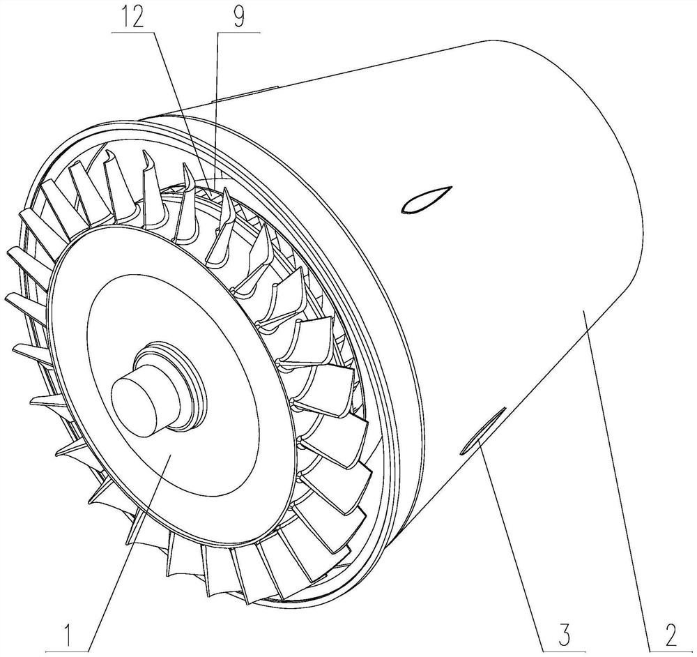
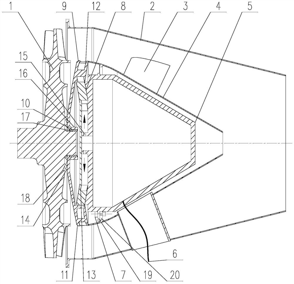
[0052] Such as Figures 1 to 17 As shown, the embedded starting and rotating device of the small turbine engine of the present invention includes a gas blowing turbine assembly fixed on the tail nozzle assembly for starting the engine turbine 1 to rotate, and the gas blowing turbine assembly includes a gas blowing turbine assembly fixed on The gas generator 5 on the tail nozzle assembly and the guider 8 and the blowing turbine 9 that are all located between the gas generator 5 and the engine turbine 1, the guider 8 is provided with the inner side and the gas outlet of the gas generator 5 15 communicated with the inner gas channel 13, the edge of the blowing turbine 9 is provided with an outer gas channel 12 whose inner side communicates with the outer side of the inner gas channel 13;

[0053] After the high-temperature gas generated by the gas generator 5 passes through the deflection of the inner gas passage 13 and the outer gas passage 12, it pushes the blowing turbine 9 to...

Embodiment 2

[0062] About the matching position between the blowing turbine 9 and the engine turbine 1 in embodiment 1, the specific implementation is as follows:

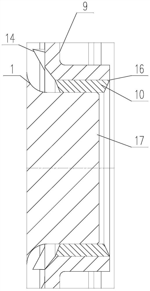
[0063] Such as figure 2 with image 3 As shown, the wear coating 10 is coated on the inner ring 16 of the blowing turbine 9 , and the thickness of the wearing coating 10 is greater than the radial gap between the blowing turbine 9 and the guide 8 .

[0064] The inner ring 16 of the blowing turbine 9 is coated with an abrasive coating 10, which forms a clearance fit with the shaft end cylinder 17 of the engine turbine 1, and can translate the blowing turbine 9 axially on the shaft end cylinder 17 of the engine turbine 1, Ensure that the meshing and disengaging axial movement of the toothed discs is not stuck.

[0065] The thickness of the wear coating 10 is greater than the radial gap between the blowing turbine 9 and the guide 8, so as to ensure that after the engine is started successfully, when the wear coating is consumed...

Embodiment 3

[0080] The implementation of the exhaust nozzle assembly is as follows:

[0081] Such as figure 2 As shown, the tail nozzle assembly includes the tail nozzle inner ring 4 sleeved on the gas generator 5, the tail nozzle outer ring 2 sleeved on the tail nozzle inner ring 4, and the tail nozzle inner ring 4 and the tail nozzle The nozzle outer ring 2 is fixedly connected to the tail nozzle support plate 3, and the gas generator 5 is connected to the tail nozzle inner ring 4 through a flange assembly, and the flange assembly is provided with a port for air flow. The guide 8 is installed on the large-diameter end of the gas generator 5 to jointly form a gas guide channel. Specifically, one channel wall of the inner gas channel 13 is formed by the end face of the gas generator 5, and the remaining channel walls are formed by the guide 8, thereby reducing Axial dimensions and weight of the small device.

[0082] Preferably, the tail nozzle support plate 3 is hollow, and the ignition...


PUM


Abstract

The invention discloses an embedded starting and rotating device of a small turbine engine and an aircraft thereof, relates to the technical field of aircrafts, and solves the technical problem that after an existing engine is successfully started, a fuel gas blowing turbine is still connected with an engine main shaft, and the power of the main shaft is continuously consumed. The starting and rotating device of the aircraft comprises a fuel gas blowing turbine assembly fixed to an exhaust nozzle assembly. The fuel gas blowing turbine assembly comprises a fuel gas generator fixed to the exhaust nozzle assembly, a guider with an inner fuel gas channel and a blowing turbine with an outer fuel gas channel. After high-temperature fuel gas is turned and deflected through the inner fuel gas channel and the outer fuel gas channel, the blowing turbine is pushed to be axially meshed with the engine turbine, and rotation of the engine turbine is completed. A notch is formed in the blowing turbine. After the engine is successfully started, the device can be completely separated by means of the pressure difference of an air system during operation of the engine, the power balance of an original rotor system of the engine is not influenced, and the power loss is reduced.

Description

technical field [0001] The present invention relates to the technical field of aircraft, and more specifically relates to the technical field of turbine engine starting belt transmission. Background technique [0002] Small turbine engines are commonly used in aircraft such as cruise missiles and target drones. In addition to the conventional rolling form, the launching methods of the aircraft also have other forms such as ejection, rocket boosting, and air delivery. However, launch methods such as ejection, rocket boosting, and air delivery require small turbine engines to ignite in the air. [0003] Based on the performance of the aircraft, this type of launching method requires a short start-up time of the small turbine engine and high reliability requirements. In order to meet the requirements of the above application characteristics, small turbine engines often use a special gas blowing turbine and a corresponding gas generator to achieve the purpose of quickly and re...

Claims


Application Information

Patent Timeline
Patent Type & Authority Applications(China)
IPC IPC(8): F02C7/277F02C7/32F01D9/04F01D5/02F02C6/20B64D27/10
CPCF02C7/277F02C7/32F01D9/04F01D5/02F02C6/20B64D27/10F05D2300/611Y02T10/12
Inventor 孟春潮刘驰熊杰贺小飞邓延波李吉祥张彪伍兵
Owner SICHUAN AEROSPACE ZHONGTIAN POWER EQUIP CO LTD
Learn More