Point-Source Model for Simulating Near-Field Effects From Structures of an Antenna

A technology of antenna structure and source model, applied in antennas, antenna arrays, antenna components, etc., to solve problems such as inability to simulate electromagnetic interactions

Pending Publication Date: 2022-01-07
APTIV TECH LTD
View PDF0 Cites 0 Cited by
  • Summary
  • Abstract
  • Description
  • Claims
  • Application Information

AI Technical Summary

Problems solved by technology

However, these asymptotic numerical methods cannot model electromagnetic interactions with antenna structures and interacting structures located in the near-field region of the active element

Method used


Image

  • Point-Source Model for Simulating Near-Field Effects From Structures of an Antenna
  • Point-Source Model for Simulating Near-Field Effects From Structures of an Antenna
  • Point-Source Model for Simulating Near-Field Effects From Structures of an Antenna

Examples


example 1

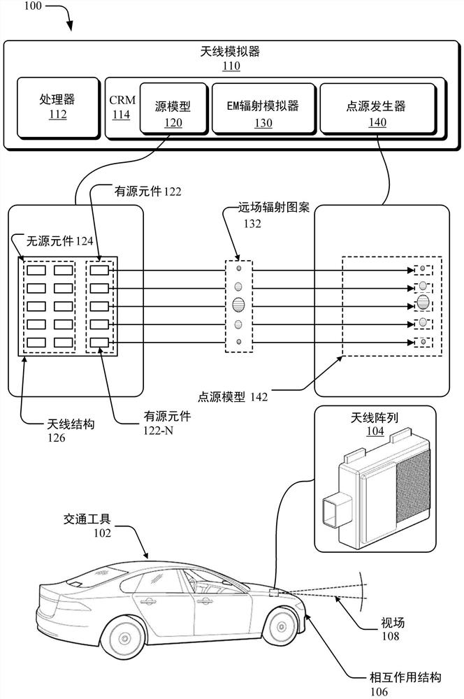
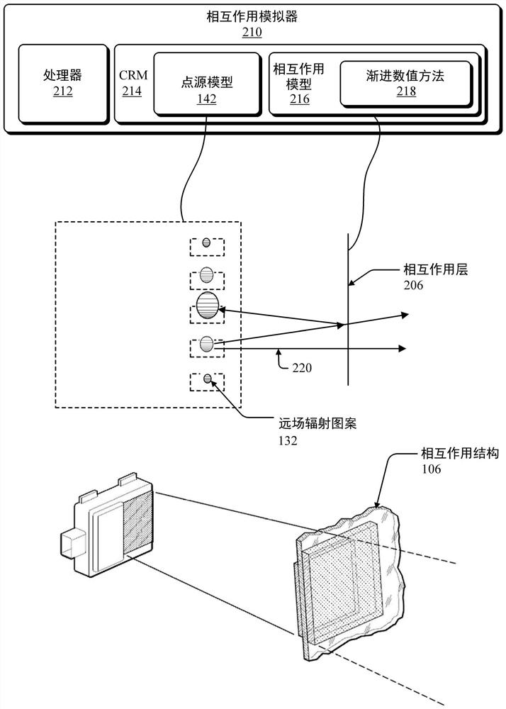
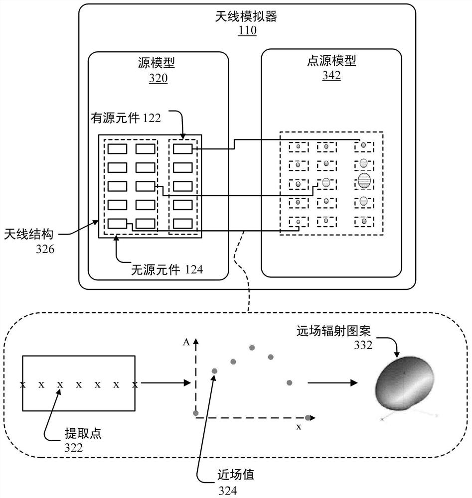
[0064] Example 1: A method for generating a point source model of an antenna array comprising: generating a source model that models at least two active elements of the antenna array and an antenna structure of the antenna array; The electromagnetic radiation field radiated by the element into space, the simulation is based on the antenna structure modeled at a certain position in the electromagnetic radiation field; based on the interaction between the electromagnetic radiation field and the antenna structure, at least one near field values; generate a far-field radiation pattern for each active element, the generation being based on a near-field to far-field transformation of the near-field values ​​of the respective active elements; and output a far-field radiation pattern that is useful for using An asymptotic numerical method is available for modeling the electromagnetic interaction between the antenna array and the at least one interacting structure, the asymptotic numeri...

example 2

[0065] Example 2: The method of Example 1, wherein the antenna structure of the source model includes a surface of the antenna array, a circuit board of the antenna array, a ground plane of the antenna array, a radome of the antenna array, a housing of the antenna array, or a passive element of the antenna array at least one of the

example 3

[0066]Example 3: The method of Example 2, wherein the antenna structure comprises: at least two passive elements, and at least one of said surface, circuit board, ground plane, radome, or housing; the method further comprising: based on an electromagnetic radiation field and interaction of the antenna structure, extracting at least one near-field value for each passive element; and generating a far-field radiation pattern for each passive element separately, the generation being based on a near-field analysis of the near-field value of the corresponding passive element to far-field transformation; and wherein the outputting of the far-field radiation pattern includes outputting the far-field radiation pattern of the active element and the far-field radiation pattern of the passive element.


PUM


Abstract

This document describes techniques and systems to generate a point-source model for simulating near-field effects from structures of an antenna. The techniques and systems generate, based on near-field values extracted from electromagnetic simulations, respective far-field radiation patterns for active elements and, in some cases, passive elements of the antenna array. The far-field radiation patterns account for electromagnetic interactions between the active elements and an antenna structure, which can include passive elements of the antenna array. The techniques and systems output the far-field radiation patterns, which are effective to simulate, using an asymptotic numerical method, electromagnetic interactions between the antenna array and at least one interaction structure. Using the described point-source model, engineers can quickly and accurately simulate electromagnetic interactions between the antenna array and the interaction structure for various configurations and applications of the antenna array.

Description

Background technique [0001] Antennas are used in a variety of applications and configurations for transmitting and receiving electromagnetic signals, such as in radar systems for detecting and tracking objects. An antenna array includes a combination of active and passive elements for transmitting and receiving electromagnetic radiation, and an antenna structure that may include a circuit board, reflective surface, ground plane, radome, or housing. Antenna arrays are often located near other structures (eg, behind a vehicle bumper), and electromagnetic radiation from active components interacts with the antenna array. The antenna structures and interacting structures located in the near-field region of the antenna array have a significant impact on the electromagnetic characteristics and performance of the antenna array. [0002] To optimize antenna placement and configuration for various applications, engineers simulate antenna arrays and their nearby interacting structures....

Claims


Application Information

Patent Timeline
Patent Type & Authority Applications(China)
IPC IPC(8): G06F30/20H01Q21/00G06F111/10
CPCG06F30/20H01Q21/00G06F2111/10H01Q1/3233H01Q21/06H01Q25/00H01Q1/528H04B17/345H04B17/373H04B17/3912H04B17/3913
Inventor B·F·坎普斯拉加
Owner APTIV TECH LTD
Why Eureka
Try Eureka