Automatic inductor winding machine and cross winding method applied to winding machine

An automatic winding machine and automatic winding technology, which is applied in the manufacture of inductors/transformers/magnets, circuits, coils, etc., can solve the problems of requiring more manpower, low efficiency, and the inability to realize the cross-winding method, so as to ensure the production The effect of quality and efficiency improvement

Pending Publication Date: 2022-01-07
ZHUHAI KLES MACHINE TECH
View PDF0 Cites 5 Cited by
  • Summary
  • Abstract
  • Description
  • Claims
  • Application Information

AI Technical Summary

Problems solved by technology

[0003] At present, the winding of the magnetic ring inductance is mostly done manually. The magnetic ring is manually fixed on the winding table, and the magnetic ring is generally fixed by the clamp, and then the enameled wire is wound on the magnetic ring one by one. Then take off the product and turn it over to fix it, and repeat the winding of the other half of the magnetic ring. This method is inefficient and requires more manpower, and the density of the winding cannot be guaranteed to be consistent.
There are also winding machines on the market for winding, but at this stage, the winding machine can only perform one-wire or two-wire winding, and cannot realize the cross-winding method.

Method used


Image

  • Automatic inductor winding machine and cross winding method applied to winding machine
  • Automatic inductor winding machine and cross winding method applied to winding machine
  • Automatic inductor winding machine and cross winding method applied to winding machine

Examples


Embodiment Construction

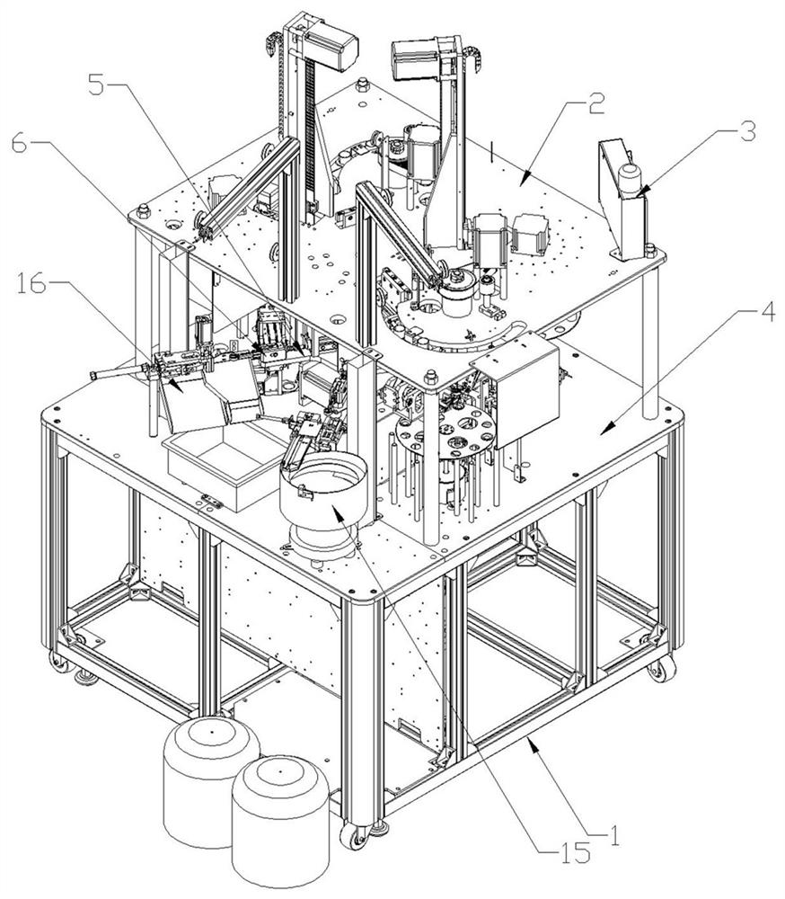
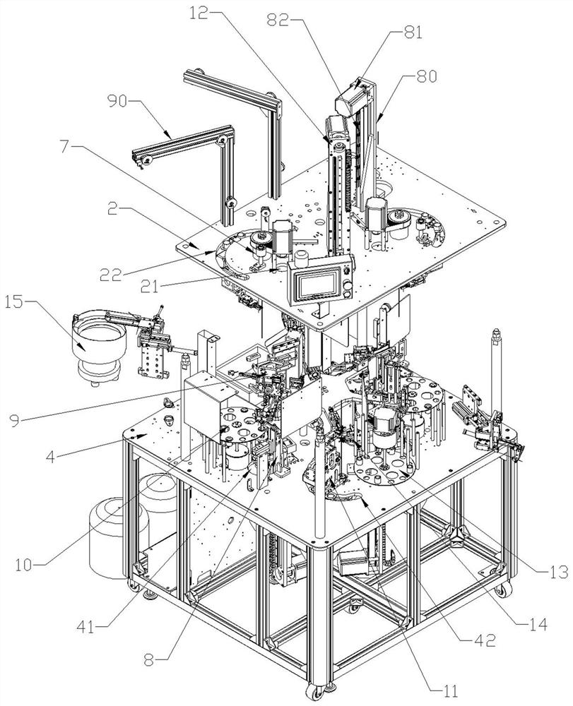
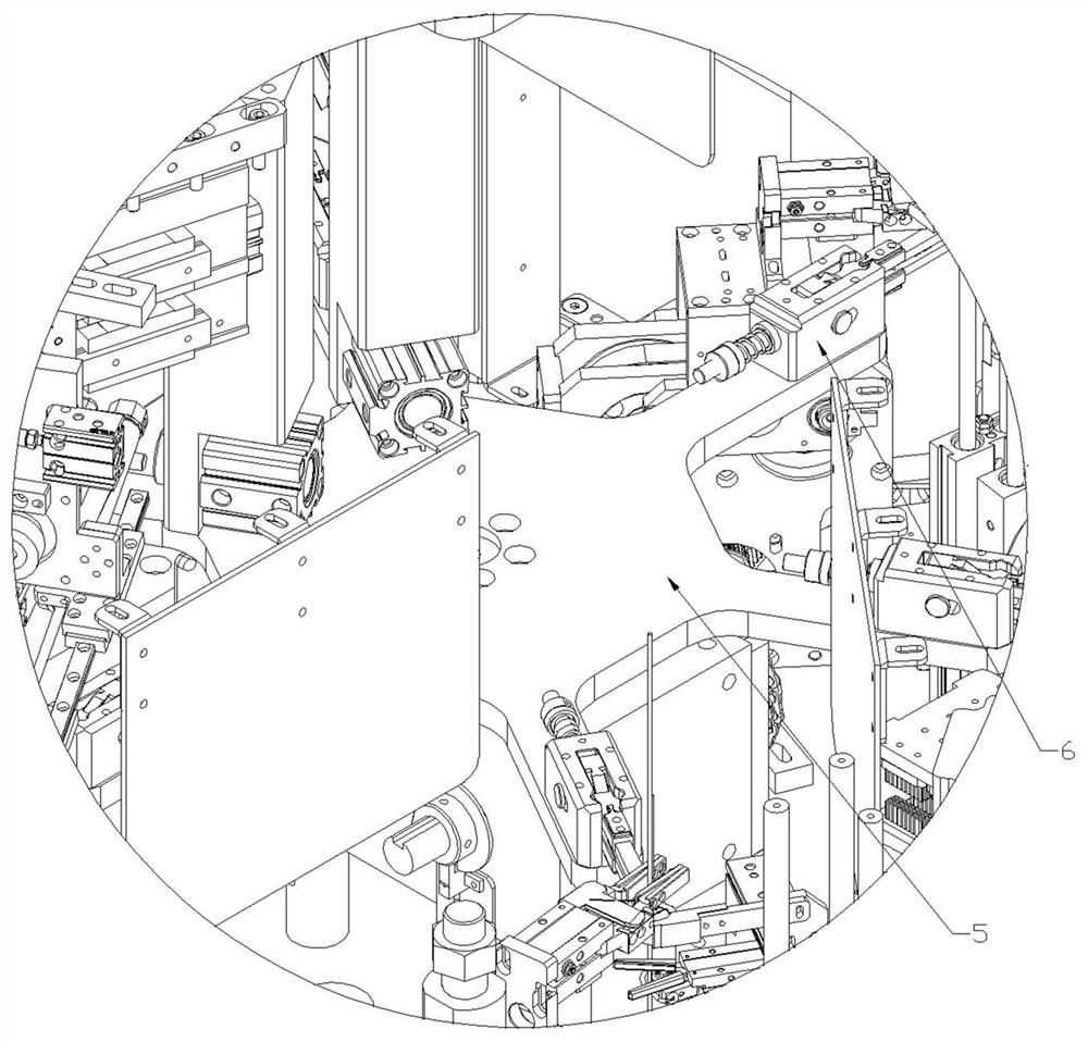
[0038] Such as figure 1 , figure 2 and image 3 As shown, the present invention includes a frame 1, a control panel 3 arranged on the top plate 2 of the frame 1, a feeding turntable 5 is rotated on the mounting plate 4 of the frame 1, and a rotating disk 5 is arranged on the mounting plate 4 around the The feeding turntable 5 is sequentially provided with a feeding mechanism, at least one set of automatic winding modules and a blanking mechanism, the automatic winding modules include a first winding station and a second winding station, and the feeding The turntable 5 is provided with a number of gripping manipulators 6, and the setting positions of the gripping manipulators 6 correspond to the feeding mechanism, at least one set of the automatic winding modules and the feeding mechanism, and the control panel 3 is electrically connected with the feeding turntable 5, the feeding mechanism, at least one set of the automatic winding module, the feeding mechanism and the clamp...


PUM


Abstract

The invention aims to provide an automatic inductor winding machine which effectively replaces manual winding, greatly improves the inductor winding efficiency and the winding density control force, and can automatically wind an inductor through a cross winding method and a cross winding method applied to the winding machine. The winding machine comprises a rack and a control panel arranged on a top plate of the rack, wherein a feeding turntable is rotationally arranged on a mounting plate of the rack, a feeding mechanism, at least one set of automatic winding module and a discharging mechanism are sequentially arranged on the mounting plate around the feeding turntable, the automatic winding module comprises a first winding station and a second winding station, a plurality of clamping manipulators are arranged on the feeding turntable, the arrangement positions of the clamping manipulators correspond to the feeding mechanism, the at least one set of automatic winding module and the discharging mechanism, and the control panel is electrically connected with the feeding turntable, the feeding mechanism, the at least one set of automatic winding module, the discharging mechanism and the clamping manipulators. The automatic inductor winding machine can be applied to the field of inductor processing.

Description

technical field [0001] The invention relates to an inductance winding device and method, in particular to an inductance automatic winding machine and a cross winding method applied to the winding machine. Background technique [0002] Inductors are components that can convert electrical energy into magnetic energy and store them. The structure of an inductor is similar to a transformer, but there is only one winding. The magnetic ring inductance is made of a coil wound on a magnetic ring. A line from the beginning to the end is a differential mode Inductance, two wires are double-wired or wound separately on both sides, which is a common-mode inductor. For general magnetic ring inductance, when the number of turns is small, it is wound from the beginning to the end in a single layer, and when the wire is long enough, it is wound from the middle to the two ends respectively. At the same time, the length of the wire that needs to pass through the magnetic ring is shortened by...

Claims


Application Information

Patent Timeline
IPC IPC(8): H01F41/08H01F41/06H01F41/096
CPCH01F41/08H01F41/06H01F41/096
Inventor 吴金辉林鸿森
Owner ZHUHAI KLES MACHINE TECH
Why Eureka
Try Eureka