Integrated wear-free low-impedance switch cabinet air chamber based on main switch loop

A wear-free, main switch technology, applied in the field of switchgear, can solve the problems of enhanced process difficulty in the remanufacturing process, large volume of air-insulated switchgear, and damage to the structural integrity of the air chamber, so as to preserve the structural integrity and reduce assembly work The effect of increasing the quantity, improving the versatility and the degree of standardization

Pending Publication Date: 2022-01-07
BEIJING CREATIVE DISTRIBUTION AUTOMATION
View PDF0 Cites 0 Cited by
  • Summary
  • Abstract
  • Description
  • Claims
  • Application Information

AI Technical Summary

Problems solved by technology

[0003] Although the medium-voltage switchgear mentioned above solves the problem of excessive volume of the air-insulated switchgear, there are still some defects
Since the air chamber is formed by setting insulating partitions, in order to ensure the stability of the installation of the components, all the components are scattered and welded inside the air chamber, which increases the difficulty of the remanufacturing process and increases the process steps
Therefore, the medium-voltage switchgear in the prior art has the following problems: first, it cannot be repaired on site during operation, and it is difficult or impossible to maintain when a fault occurs; second, because the gas chamber and components need to be welded, resulting in The structural integrity of the gas chamber is damaged, and the internal pressure is likely to cause deformation of the outer wall of the gas chamber. The deformed gas chamber will affect the internal components, and the switch will refuse to move. High, metal powder is produced after long-term operation of the switch, causing insulation damage and other difficult problems

Method used


Image

  • Integrated wear-free low-impedance switch cabinet air chamber based on main switch loop
  • Integrated wear-free low-impedance switch cabinet air chamber based on main switch loop
  • Integrated wear-free low-impedance switch cabinet air chamber based on main switch loop

Examples


Embodiment Construction

[0026] The present invention is further described in conjunction with the following examples.

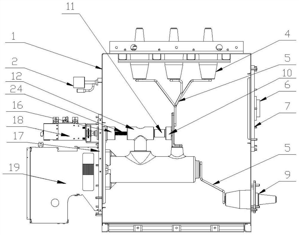
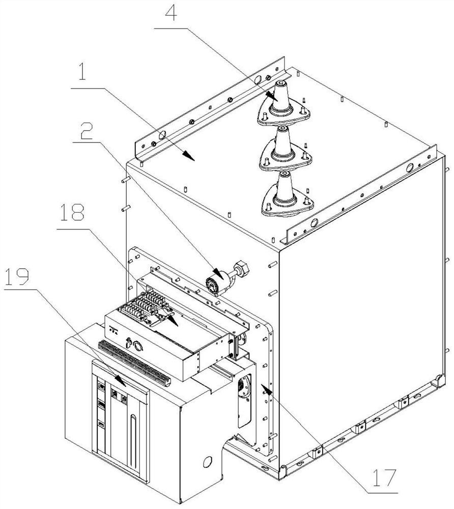
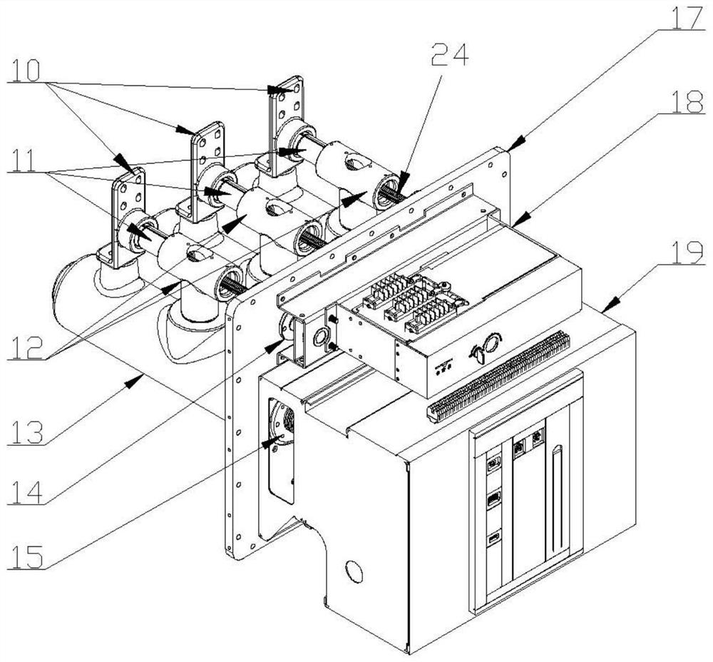
[0027] For a specific implementation of the gas chamber of a switchgear based on the integration of the main switch circuit without wear and low impedance of the present invention, please refer to figure 1 The air chamber includes an air chamber housing 1, and the left side, right side and upper side of the air chamber housing 1 are respectively sealed and fixed with a reference flange 17, a second outer tapered sleeve 9 and a first outer tapered sleeve 4. It should be noted that the side of the gas chamber housing 1 where the reference flange 17 is installed is provided with an opening for inserting the flange of the reference flange 17, and the skirt of the reference flange 17 is fixed on the outer surface of the gas chamber housing 1 by bolts. , using the locking force of the bolts to make the reference flange 17 close to the left side of the air chamber housing 1 . In order to ...


PUM


Abstract

The invention relates to the technical field of switch cabinets, in particular to an integrated wear-free low-impedance switch cabinet air chamber based on a main switch loop. The switch cabinet air chamber comprises an air chamber shell, wherein a reference flange, a second outer conical sleeve and a first outer conical sleeve are respectively and fixedly mounted on the left side surface, the right side surface and the upper side surface of the air chamber shell in a sealing manner, the right side surface of the reference flange is fixedly provided with a solid-sealed polar pole and a grounding static contact, the upper end of the solid-sealed polar pole is fixedly provided with an isolation three-way static contact and an isolation static contact, the isolation three-way static contact is provided with a lead screw in a penetrating manner, and one end of the lead screw is sleeved with an isolation moving contact; and an isolation switch mechanism and a circuit breaker mechanism are fixedly installed on the left side surface of the reference flange, the isolation static contact is electrically connected with the first outer conical sleeve, the solid-sealed polar pole is electrically connected with the second outer conical sleeve, and the outer side of the reference flange is grounded. Compared with the prior art, the structural design and the assembly mode of the air chamber are simplified, and the problems of high impedance, troublesome disassembly, assembly and maintenance, switch failure and the like in the prior art are solved.

Description

technical field [0001] The invention relates to the technical field of switch cabinets, in particular to a switch cabinet air chamber based on the integration of main switch circuits without wear and low impedance. Background technique [0002] Traditional medium-voltage switchgear generally adopts air insulation technology. In order to ensure the safe operation of switchgear, a large enough air clearance is required. This type of switchgear will have relatively large dimensions, especially in high salt spray, high humidity, Under harsh environments such as high altitudes, the requirements for the air clearance of the switchgear are further increased, resulting in a further increase in the overall size of the switchgear. In order to solve the problem of excessive size, some switchgears adopt composite insulation technology, that is, add insulating partitions in the air gap to form air chambers. This type of structure can reduce the overall size of the switchgear while meetin...

Claims


Application Information

Patent Timeline
Patent Type & Authority Applications(China)
IPC IPC(8): H02B13/035H02B13/025
CPCH02B13/035H02B13/025
Inventor 张鹏飞刘沛沛孙云飞刘磊张丽超季慧峰
Owner BEIJING CREATIVE DISTRIBUTION AUTOMATION
Why Eureka
Try Eureka