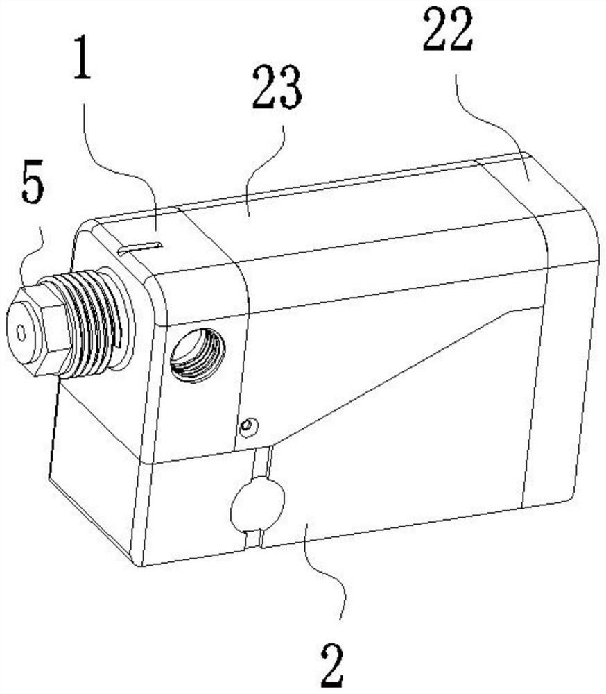
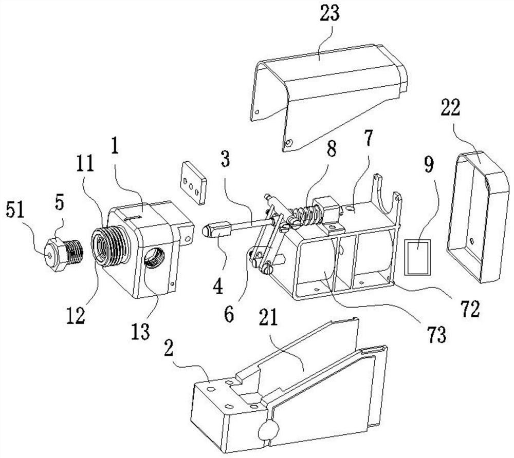
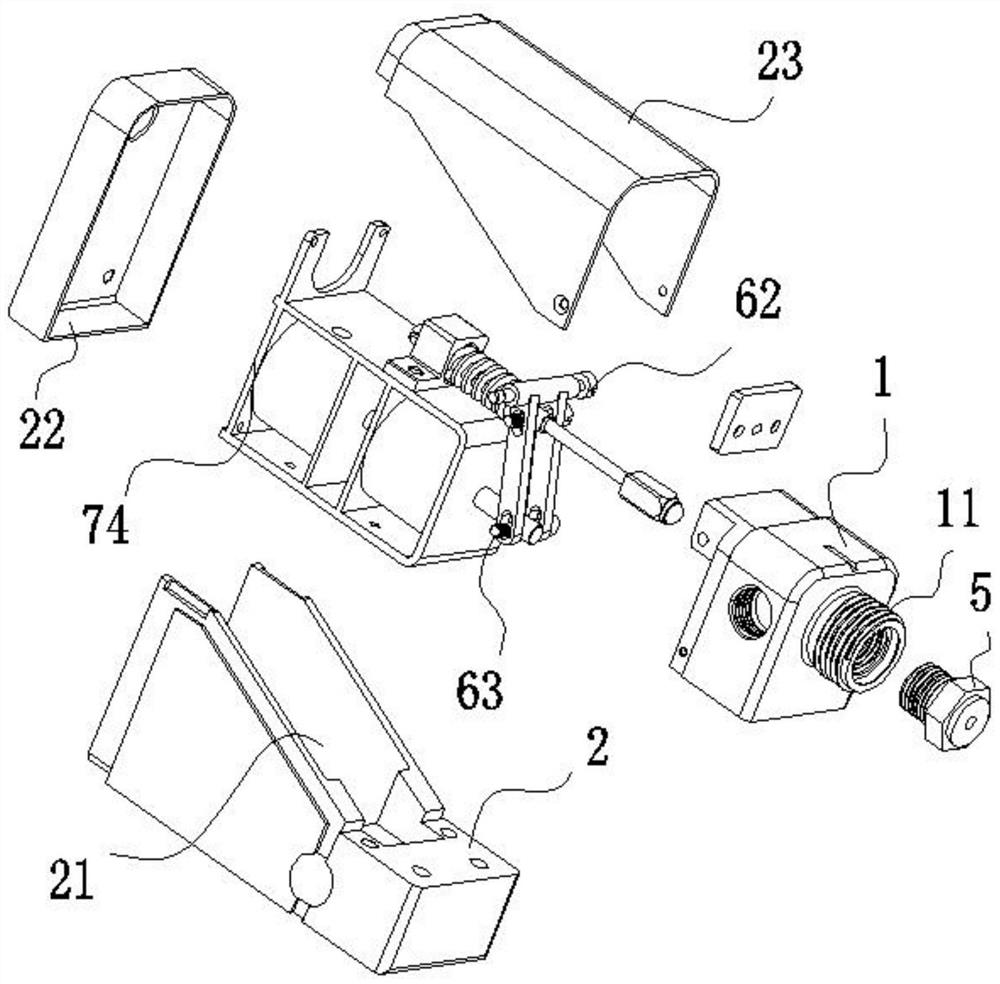
Airless automatic spray gun employing electromagnet to drive switch-on and switch-off movements

A technology of automatic spray guns and electromagnets, applied in spraying devices, liquid spraying devices, etc., can solve problems such as limited space for platform carrying equipment, flammable and explosive high-pressure gas sources, and difficulties in obtaining high-pressure gas sources, achieving outstanding economy, The effect of outstanding practicability and compact structure

Pending Publication Date: 2022-01-11
珠海市睿涂智能科技有限公司
View PDF0 Cites 0 Cited by
  • Summary
  • Abstract
  • Description
  • Claims
  • Application Information

AI Technical Summary

Problems solved by technology

[0003] But in recent years, with the improvement of automation technology and the diversification of application scenarios, many applications that require the use of automatic spray guns are based on independent mobile robot platforms, and the application scenarios are not limited to factory workshops, and it is difficult to obtain high-pressure air sources
In particular, most independent mobile platforms are driven by batteries, the battery life is limited, the space for carrying equipment on the platform is limited, and the high-pressure gas source has potential safety hazards of flammability and explosion.
making gas supplied by a compressor or stored in a high pressure tank not the optimal solution for this type of application
[0004] At the same time, with the increasing demand for energy saving and emission reduction in the society, the gas source preparation of traditional spraying production lines produces huge energy consumption. The energy saving and emission reduction of spraying companies requires a new alternative solution for process equipment

Method used


Image

  • Airless automatic spray gun employing electromagnet to drive switch-on and switch-off movements
  • Airless automatic spray gun employing electromagnet to drive switch-on and switch-off movements
  • Airless automatic spray gun employing electromagnet to drive switch-on and switch-off movements

Examples


Embodiment Construction

[0024] Embodiments of the present invention are described in detail below, examples of which are shown in the drawings, wherein the same or similar reference numerals represent the same or similar elements or elements having the same or similar functions throughout.

[0025] The orientations shown in the drawings should not be construed as limiting the specific protection scope of the present invention, but are only for reference and understanding of preferred embodiments, and the product components shown in the drawings can be changed in position or increased in number or simplified in structure.

[0026] The "connection" described in the specification and the "connection" relationship between the parts shown in the drawings can be understood as fixed connection or detachable connection or integral connection; it can be directly connected or connected through an intermediary. Those of ordinary skill in the art can understand the connection relationship according to the specifi...


PUM


Abstract

An airless automatic spray gun employing an electromagnet to drive switch-on and switch-off movements comprises a gun body, a gun base, a gun needle rod, a gun head, a gun head cap, a transmission device, a self-holding electromagnet, an elastic assembly and a programmable controller, the gun head is located in the gun body, and the transmission device is connected between the gun needle rod and the self-holding electromagnet. Power transmission is carried out through the transmission device, and the self-holding electromagnet provides the movement execution force and the state keeping force for on-off movements of the whole spray gun under the control of the programmable controller; the elastic assembly is located at the rear end of the gun head and provides locking and the flexible feeding movement execution force so that the gun head and the gun head cap are kept in a sealed state under the rated spraying liquid working pressure, and extra power except the self-holding electromagnet is provided when the gun head executes the switch-off movement; the airless automatic spray gun is driven by the electromagnet to perform switch-on and switch-off movements; and the device has the characteristics of low power consumption, compact structure, quick operation movement, programmable and IO control, flexible operation, high applicability and the like.

Description

technical field [0001] The invention relates to an airless automatic spray gun which uses an electromagnet to drive the opening and closing action of the gun Background technique [0002] For a long time, various fluid material automatic control spray guns used in industry have used a pneumatic piston mechanism to drive the opening and closing of the automatic spray gun. Specifically: a steel spray needle is installed in front of the piston, and a steel spray needle is installed behind the piston. There is a set of high-tension springs, when the supply of compressed air is stopped, the spring pushes the piston and the spray needle forward, at this time, the spray needle and the nozzle cap are closely matched with high precision to block the passage of liquid, otherwise, when the compressed air When the supply starts, the pressure of the compressed air pushes the piston away, creating a gap between the spray needle and the nozzle cap to allow the high-pressure liquid to spray...

Claims


Application Information

Patent Timeline
Patent Type & Authority Applications(China)
IPC IPC(8): B05B9/01B05B12/00
CPCB05B9/01B05B12/00B05B12/002
Inventor 赵白桦杨安萍
Owner 珠海市睿涂智能科技有限公司
Why Eureka
Try Eureka