Rapid forming device for thin-wall parts
A forming device and technology for thin-walled parts, which is applied in the field of rapid prototyping devices for thin-walled parts, can solve the problems that the theoretical shape and the skin surface cannot be completely fitted, there are many uncontrollable factors, and the operation is complicated, and the structure is simple and reliable. The effect of type stability and wide versatility
- Summary
- Abstract
- Description
- Claims
- Application Information
AI Technical Summary
Problems solved by technology
Method used
Image

Examples
Embodiment Construction
[0019] In order to make the technical means, creative features, goals and effects achieved by the present invention easy to understand, the present invention will be further described below in conjunction with specific illustrations.
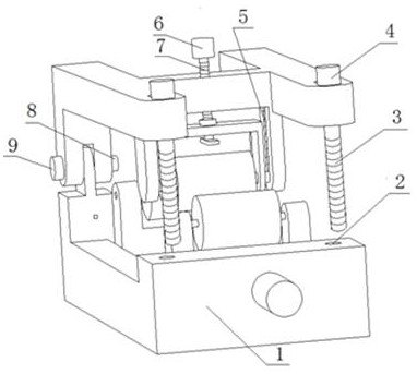
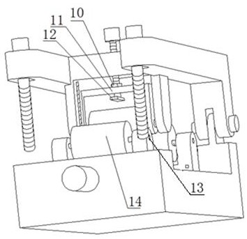
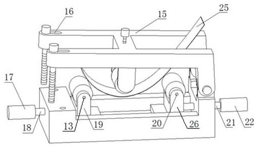
[0020] see Figure 1~4 A rapid prototyping device for thin-walled parts, including a base 1, a clamping hole 2, a bolt 3, a nut 4, a guide rail 5, an adjusting nut 6, an adjusting bolt 7, a connecting bolt 8, a connecting nut 9, and a fastening nut 10 , support frame 11, fixed block 12, front roller 13, front roller 14, adjustment bracket 15, clamping groove 16, front handle 17, front moving bolt 18, front support 19, rear roller 20, rear moving bolt 21. Rear handle 22, vertical roller 23, rear roller 24, thin-walled parts 25 and rear support 26, wherein one end of the base 1 is connected to one end of the adjustment bracket 15 through a connecting bolt 8 and a connecting nut 9, so The other end of the adjustment bracket 15 is symmetrically pro...
PUM
 Abstract
Description
Claims
Application Information
 - Generate Ideas
- Intellectual Property
- Life Sciences
- Materials
- Tech Scout
- Unparalleled Data Quality
- Higher Quality Content
- 60% Fewer Hallucinations
Browse by: Latest US Patents, China's latest patents, Technical Efficacy Thesaurus, Application Domain, Technology Topic, Popular Technical Reports.
© 2025 PatSnap. All rights reserved.Legal|Privacy policy|Modern Slavery Act Transparency Statement|Sitemap|About US| Contact US: help@patsnap.com