Liquefied gas transport ship
A technology for transporting ships and liquefied petroleum gas, which is applied in the directions of transportation and packaging, hulls, and ship construction. It can solve problems affecting ship blind spots, high costs, and unfavorable ship stability, and achieve good floating stability and little change in draft. , cost-saving effect
- Summary
- Abstract
- Description
- Claims
- Application Information
AI Technical Summary
Problems solved by technology
Method used
Image

Examples
Embodiment 1
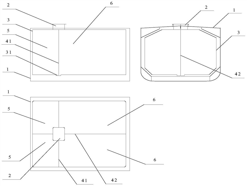
[0039] For small liquefied gas carriers, such as figure 1 As shown, according to the requirements of endurance, the transverse bulkhead 41 extends along the entire width of the liquid tank 3, and the longitudinal bulkhead 42 extends along the entire length of the liquid tank 3, and is located on the center line of the liquid tank 3. From a top view, both Arranged in a cross shape, the liquid tank 3 is divided into two fuel areas 5 and two liquid cargo areas 6, and the two fuel areas 5 can meet the endurance requirements of a small liquefied gas carrier. The air chamber 2 is located directly above the intersection of the transverse bulkhead 41 and the longitudinal bulkhead 42 , and the tops of the two fuel areas 5 and the two liquid cargo areas 6 are connected to the air chamber 2 . At the bottom of the liquid tank 3 , directly below the air chamber 2 , there is also a liquid collecting tank 31 located at the intersection of the transverse bulkhead 41 and the longitudinal bulkh...
Embodiment 2
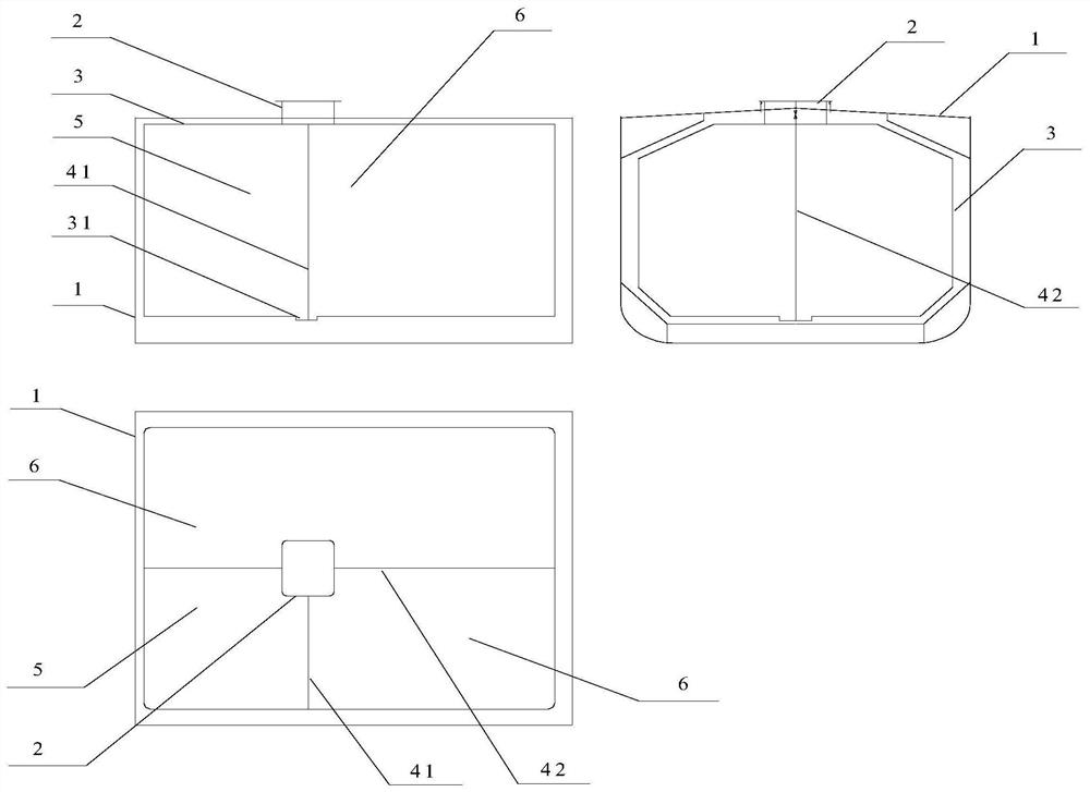
[0041] For medium-sized liquefied gas carriers, such as figure 2 As shown, according to the requirement of endurance, the transverse bulkhead 41 is connected between the longitudinal bulkhead 42 and a side wall of the liquid tank 3, and the longitudinal bulkhead 42 extends along the entire length of the liquid tank 3 and is located on the centerline of the liquid tank 3, Viewed from a top view, the two are arranged in a T-shape, dividing the liquid tank 3 into a fuel area 5 and two liquid cargo areas 6 . The air chamber 2 is located directly above the junction of the transverse bulkhead 41 and the longitudinal bulkhead 42 , and the tops of a fuel area 5 and two liquid cargo areas 6 are connected to the air chamber 2 . At the bottom of the liquid tank 3, directly below the air chamber 2, there is also a sump 31 located at the intersection of the transverse bulkhead 41 and the longitudinal bulkhead 42. Extending to the bottom of the sump 31, the liquid cargo entering the sump ...
Embodiment 3
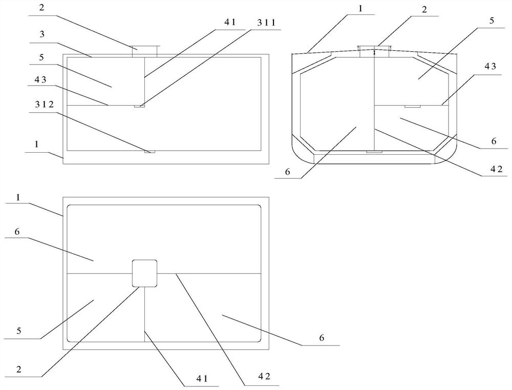
[0043] For large liquefied gas carriers, such as image 3 As shown, according to the requirement of endurance, the transverse bulkhead 41 is connected between the longitudinal bulkhead 42 and a side wall of the liquid tank 3, and the longitudinal bulkhead 42 extends along the entire length of the liquid tank 3 and is located on the centerline of the liquid tank 3, Viewed from a top view, the transverse bulkhead 41 and the longitudinal bulkhead 42 are arranged in a T shape, dividing the liquid tank 3 into a fuel area 5 and two liquid cargo areas 6, and a horizontal bulkhead 43 is provided at the bottom of the fuel area 5, wherein A cargo area 6 extends below the horizontal bulkhead 43 . The air chamber 2 is located directly above the junction of the transverse bulkhead 41 and the longitudinal bulkhead 42 , and the tops of a fuel area 5 and two liquid cargo areas 6 are connected to the air chamber 2 . A first liquid collection tank 311 is provided at the bottom of the fuel area...
PUM
 Abstract
Description
Claims
Application Information
 - R&D
- Intellectual Property
- Life Sciences
- Materials
- Tech Scout
- Unparalleled Data Quality
- Higher Quality Content
- 60% Fewer Hallucinations
Browse by: Latest US Patents, China's latest patents, Technical Efficacy Thesaurus, Application Domain, Technology Topic, Popular Technical Reports.
© 2025 PatSnap. All rights reserved.Legal|Privacy policy|Modern Slavery Act Transparency Statement|Sitemap|About US| Contact US: help@patsnap.com