Counter-rotating secondary fan silencing system

A rotary and noise reduction technology, applied in non-variable pumps, ventilation of mines/tunnels, mining equipment, etc., can solve problems affecting the ventilation efficiency of fans and achieve the effect of improving comfort

Pending Publication Date: 2022-01-11
安徽三星环保工程有限公司
View PDF0 Cites 0 Cited by
  • Summary
  • Abstract
  • Description
  • Claims
  • Application Information

AI Technical Summary

Problems solved by technology

However, its reduction has not reached below the 85dB stipulated by the state. Most equipment can only reduce within 14dB, always exceeding 85dB. Moreover, in the process of pursuing noise reduction, some will affect the fan ventilation efficiency.

Method used


Image

  • Counter-rotating secondary fan silencing system
  • Counter-rotating secondary fan silencing system

Examples


Embodiment 1

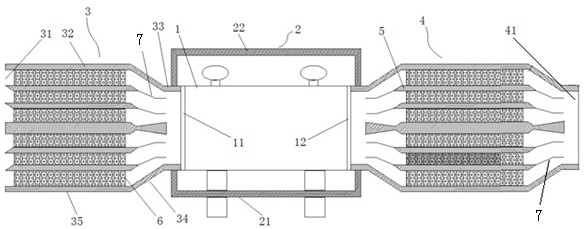
[0021] Such as figure 1 As shown, a counter-rotating local fan silencing system includes a box cover 2 in which the local fan 1 is placed, a cavity-expanding air-inducing muffler 3 installed at the air inlet 11 of the local fan, and a muffler 3 installed at the air outlet 12 of the local fan. The radius of the air inlet 31 of the expanded cavity muffler 3 is greater than the radius of the connection end with the local fan air inlet 11, and the radius of the air outlet end 41 of the expanded cavity muffler is equal to The radius of the connection end with the local fan air outlet 12 is provided with a sound-absorbing layer 5 in the housing inner wall and inner cavity of the enlarged cavity induced wind muffler 3 and the expanded cavity air outlet muffler 4 .

[0022] The distance between different sound-absorbing layers is proportional to the layer thickness of the sound-absorbing layer. The production of the sound-absorbing layer is not arbitrary, and its thickness and length...

Embodiment 2

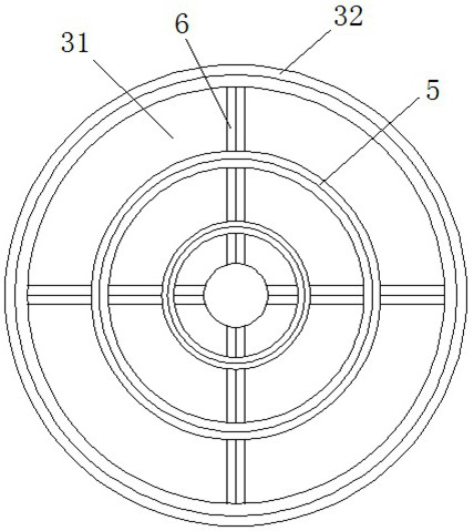
[0027] As a preferred design of Embodiment 1, the cavity-enlarging air-induced wind muffler 3 includes an outer shell 32 with a hollow inner cavity and openings at both ends, and a sound-absorbing layer 5 installed in the hollow inner cavity of the outer shell 32. The outer shell 32 is The sound-absorbing structure inside the outer compartment, the air-enlarging muffler 3 is divided into a connecting section 33, a flared section 34 and a sound-absorbing section 35 connected in sequence, wherein the end of the connecting section 33 is connected to the local fan air inlet 11 through a flange, The flaring section 34 is a conical frustum or a truss, and an air deflector 7 is arranged inside to guide the wind into the muffler section 35. The sound absorbing layer 5 provided in the muffler section 35 is connected with the air deflector 7 correspondingly. Between different sound absorbing layers 5 , and the sound-absorbing layer 5 is connected to the outer casing 32 through the suppor...


PUM


Abstract

The invention discloses a counter-rotating secondary fan silencing system which comprises a box body cover in which a secondary fan is arranged, a cavity expanding air inducing silencer installed at an air inlet of the secondary fan and a cavity expanding air outlet silencer installed at an air outlet of the secondary fan. The radius of an air inducing inlet of the cavity expanding air inducing silencer is larger than that of the end, connected with the air inlet of the secondary fan, of the cavity expanding air inducing silencer. The radius of the air outlet end of the cavity expanding air outlet silencer is equal to the radius of the secondary fan air outlet connecting end, and sound absorption layers are arranged in the inner walls and the inner cavities of shells of the cavity expanding air inducing silencer and the cavity expanding air outlet silencer. The cavity expanding air inducing silencer, the cavity expanding air outlet silencer and the box body cover are combined, overall treatment is conducted on airflow vortexes, sound energy, mechanical noise and the like, under the condition that ventilation is not affected, the sound absorbing volume of 40 dB can be achieved, the minimum sound can be reduced to 70 dB, the requirement of the national standard of 85 dB or below is completely met, and normal talking and communication are not affected when personnel work at the position. And the working environment comfort of workers is improved.

Description

technical field [0001] The invention relates to a counter-rotating local fan noise reduction system, which belongs to the technical field of noise reduction equipment. Background technique [0002] Local fans commonly used in mines are referred to as local fans for short. In order to achieve higher transmission efficiency, counter-rotating fans are commonly used in the prior art. Mining local fans are one of the main noise sources in mines, and their sound value often reaches 100-110dB, which greatly exceeds the noise allowable standard stipulated by the state. Reducing noise can not only protect the health of underground workers, but also improve the underground operating environment and increase production efficiency. [0003] The noise of mining local fans is mainly aerodynamic noise generated by the fan blades hitting the air. In order to reduce the noise in the prior art, various methods have been adopted, including adjusting the structure of the blower fan, installi...

Claims


Application Information

Patent Timeline
Patent Type & Authority Applications(China)
IPC IPC(8): F04D29/66F04D29/40E21F1/00
CPCF04D29/663F04D29/664F04D29/403E21F1/006
Inventor 吴光明
Owner 安徽三星环保工程有限公司
Why Eureka
Try Eureka