
Auxiliary jig for optical fiber distribution box and optical fiber distribution box

A fiber distribution box and optical fiber technology, applied in the field of optical fibers, can solve the problems of easy damage or breakage of optical fibers, and achieve the effects of reducing damage, reducing costs, and improving efficiency

Pending Publication Date: 2022-01-11
深圳市比洋光通信科技股份有限公司
View PDF0 Cites 0 Cited by
  • Summary
  • Abstract
  • Description
  • Claims
  • Application Information

AI Technical Summary

Problems solved by technology

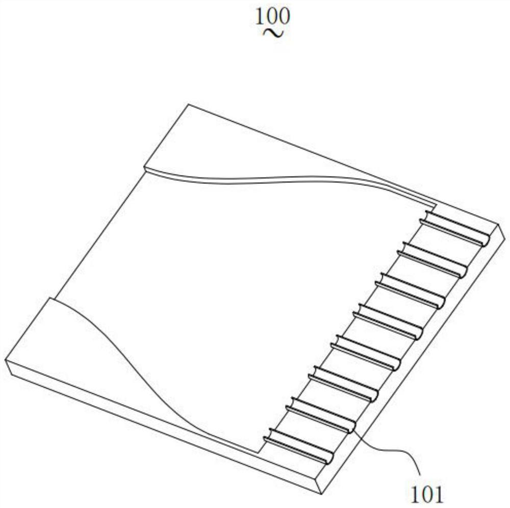
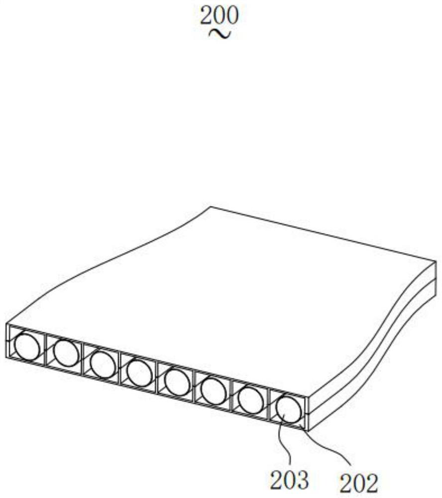
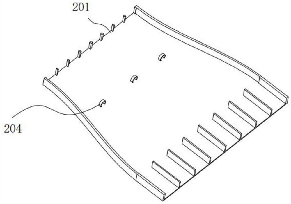
[0004] In order to overcome the technical problem that the current optical fiber splitting box is easily damaged or broken when passing through the optical fiber, the invention provides an auxiliary fixture for the optical fiber splitting box and a fiber splitting box

Method used


Image

  • Auxiliary jig for optical fiber distribution box and optical fiber distribution box
  • Auxiliary jig for optical fiber distribution box and optical fiber distribution box
  • Auxiliary jig for optical fiber distribution box and optical fiber distribution box

Examples


Embodiment Construction

[0028] In order to make the purpose, technical solutions and advantages of the present invention more clear, the present invention will be further described in detail below in conjunction with the accompanying drawings and implementation examples. It should be understood that the specific embodiments described here are only used to explain the present invention, not to limit the present invention.

[0029] It should be noted that when an element is referred to as being “fixed” to another element, it can be directly on the other element or there can also be an intervening element. When an element is referred to as being "connected to" another element, it can be directly connected to the other element or intervening elements may also be present. The terms "vertical," "horizontal," "left," "right," and similar expressions are used herein for purposes of illustration only.

[0030] With the development of the Internet and big data, the construction of large data centers is becomi...


PUM


Abstract

The invention provides an auxiliary jig for an optical fiber distribution box. The jig is used for assisting the optical fiber distribution box to arrange and classify optical fibers and comprises a jig body, and the optical fiber distribution box is detachably connected with the jig body; the jig is provided with a slot close to an optical fiber outlet of the optical fiber distribution box, and the slot is used for classifying and positioning the optical fibers. The auxiliary jig is provided with the slot, the optical fibers penetrating through the optical fiber distribution box are classified through the slot and collected in the slot, so that the optical fibers are classified before penetrating into a ceramic tube, the optical fibers penetrate into the ceramic tube in a unified mode at a time, abrasion between the optical fibers and breakage of the optical fibers caused by multiple times of penetrating into the ceramic tube are avoided, damage to the optical fibers is reduced, and the conduction efficiency of the optical fibers is improved. An optical fiber distribution box comprises an optical fiber inlet, an optical fiber outlet and a ceramic tube, and the ceramic tube is connected with the optical fiber outlet. The optical fibers enter the optical fiber distribution box from the optical fiber inlet and then penetrate out of the optical fiber distribution box from the optical fiber outlet.

Description

technical field [0001] The invention relates to the field of optical fiber technology, in particular to an auxiliary jig for an optical fiber splitting box and an optical fiber splitting box. Background technique [0002] With the development of the Internet and big data, the construction of large data centers is becoming increasingly important. The data center is composed of a large number of servers, and a large amount of data exchange is required between the servers. Optical fiber interconnection has replaced electronic interconnection and has become the most important interconnection technology in the data center. In a supercomputer system, high-speed data exchange is required between parallel computing cabinets, and optical fiber interconnection has also replaced electronic interconnection. In order to meet the demand of mass high-speed data exchange, high-density parallel optical fiber transmission modules are usually used in optical fiber interconnection technology. ...

Claims


Application Information

Patent Timeline
Patent Type & Authority Applications(China)
IPC IPC(8): G02B6/44
CPCG02B6/4471
Inventor 汤岳云毕鹏军汤榕煊陈曲张孟勇江波
Owner 深圳市比洋光通信科技股份有限公司
Learn More