

Calibration device, display chip and display
A technology for calibrating devices and comparators, which is applied in the field of circuits and can solve problems such as complex pixel structures
- Summary
- Abstract
- Description
- Claims
- Application Information
AI Technical Summary
Problems solved by technology
Method used
Image

Examples
Embodiment Construction
[0028] In order to make the above objects, features and advantages of the present invention more comprehensible, specific embodiments of the present invention will be described in detail below in conjunction with the accompanying drawings.
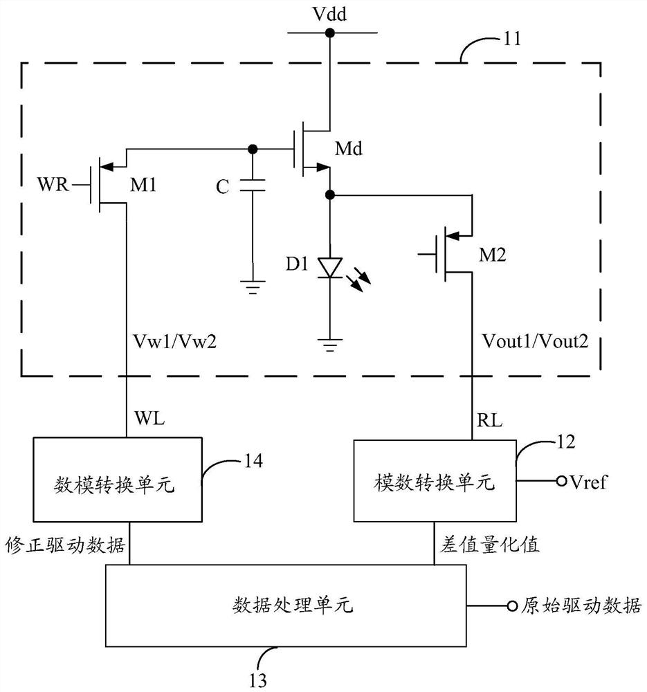
[0029] Such as figure 2 As shown, the embodiment of the present invention provides a calibration device suitable for coupling with at least one pixel unit 11 . The pixel unit 11 is adapted to receive the selection signal WR and the reference write voltage Vw1, and provide an initial output voltage Vout1 based on the reference write voltage Vw1 when the selection signal WR is at an active level.
[0030] The calibration device includes: an analog-to-digital conversion unit 12 . The analog-to-digital conversion unit 12 can obtain a first voltage difference between the reference voltage Vref and the initial output voltage Vout1, and perform analog-to-digital conversion on the first voltage difference to obtain a difference quantization valu...
PUM
 Abstract
Description
Claims
Application Information