Capacitor lead welding tool

A lead wire welding and capacitor technology, which is applied in the field of capacitor lead wire welding tooling, can solve the problems of complex equipment structure, high cost, collision of welding head, etc., and achieve the effect of improving production efficiency, simple structure, and avoiding conflict with welding head

Pending Publication Date: 2022-07-12
ANHUI FEIDA ELECTRICAL TECH CO LTD
View PDF0 Cites 0 Cited by
  • Summary
  • Abstract
  • Description
  • Claims
  • Application Information

AI Technical Summary

Problems solved by technology

When this kind of mechanical welding equipment is welding, the welding head is easy to collide with the manipulator holding the lead wire, and only some large capacitors can be welded
At the same time, this type of mechanical welding equipment needs to use a multi-degree-of-freedom manipulator to feed the wires, the equipment structure is complex, and the cost is high

Method used


Image

  • Capacitor lead welding tool
  • Capacitor lead welding tool
  • Capacitor lead welding tool

Examples


Embodiment Construction

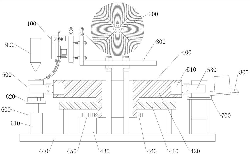
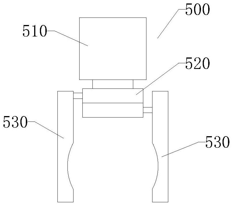
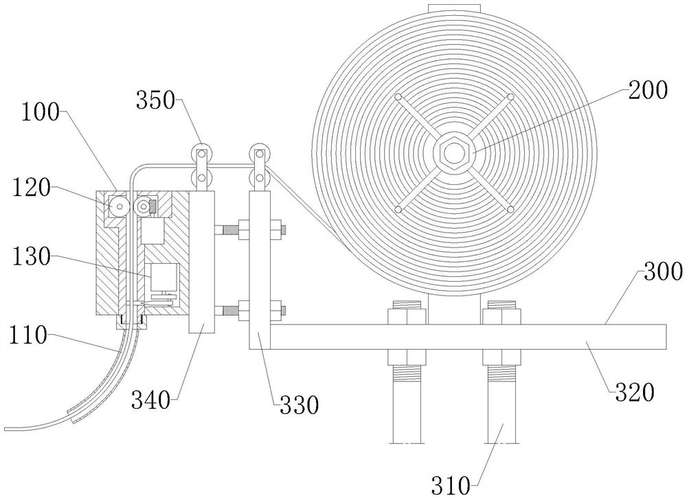
[0026] Please refer to Figure 1-6 As shown, a capacitor lead welding tool according to an embodiment of the present invention includes a capacitor core feeding mechanism and a lead wire feeding mechanism. The capacitor core feeding mechanism includes a rotating mechanism 400 and a plurality of clamping mechanisms 500. The clamping mechanisms 500 are installed on the rotating mechanism 400 and are distributed in a circular array around the center of rotation. The wire feeding mechanism includes a wire winder 200 and a wire feeding head 100 . A feeding station, a soldering station and a discharging station are arranged on the rotation circumference of the rotary mechanism 400, a conveyor 800 for conveying workpieces is arranged at the feeding station and the discharging station, and a tin welding station is arranged with Soldering equipment 900. The soldering equipment 900 generally includes a welding head and a tin feeding mechanism. The welding head can move down to the surf...


PUM


Abstract

The invention discloses a capacitor lead welding tool which comprises a capacitor core feeding mechanism and a lead feeding mechanism, the capacitor core feeding mechanism comprises a rotating mechanism and a clamping mechanism, the clamping mechanism is used for clamping a capacitor core, and the rotating mechanism can drive the clamping mechanism to rotate among a feeding station, a tin welding station and a discharging station in sequence. The clamping mechanism can drive a capacitor core to rotate by 180 degrees at a tin welding station so as to weld leads at the two ends of the capacitor core, the lead feeding mechanism comprises a lead winder and a lead feeding head, the leads are wound on the lead winder, one end of each lead is connected into the lead feeding head, and the lead feeding head is used for conveying the leads and cutting the leads into segments. The lead feeding head can convey the lead from one side of the capacitor core to the end face of the capacitor core at a tin welding station. According to the welding tool, automatic assembly line machining can be achieved, the lead can be fed from the side of the capacitor core during welding, conflict with a welding head can be avoided, and the welding position is not limited.

Description

technical field [0001] The invention relates to the technical field of capacitor welding, in particular to a capacitor lead welding tool. Background technique [0002] In the processing and production of film capacitors, it is necessary to form a metal layer on the two cylindrical end faces of the capacitor core through a gold spray process, and then weld leads on the metal layer, and the capacitor core and the shell are connected by leads. In the prior art, traditional manual welding methods or mechanical automatic welding methods are generally used. [0003] Although the traditional manual welding method has the characteristics of simple equipment and flexible operation, it has the problems of low production efficiency, poor working environment and high labor intensity. This phenomenon makes the product quality not guaranteed, and the feeding of tin wire is not easy to control, and a lot of smoke will be generated, which will affect the health of workers. [0004] In the...

Claims


Application Information

Patent Timeline
Patent Type & Authority Applications(China)
IPC IPC(8): B23K3/08B23K3/02B65H51/08B21F11/00
CPCB23K3/08B23K3/02B65H51/08B21F11/00
Inventor 胡忠胜王汝文谢成刘庆
Owner ANHUI FEIDA ELECTRICAL TECH CO LTD
Why Eureka
Try Eureka