
Automatic demolding equipment for casting high-temperature alloy bars

A high-temperature alloy and automatic demoulding technology, applied in the field of alloy casting, can solve the problems of high energy consumption of hydraulic propulsion devices and increased production costs

Pending Publication Date: 2022-01-14
泰州市锦峰新材料科技有限公司
View PDF12 Cites 0 Cited by
  • Summary
  • Abstract
  • Description
  • Claims
  • Application Information

AI Technical Summary

Problems solved by technology

[0003] At present, when the high-temperature alloy rod is demoulding, the high-temperature alloy rod is generally pushed out of the mold by using a hydraulic pusher. Since the high-temperature alloy rod is closely connected to the mold, a hydraulic pusher with a large power is required to push out the high-temperature alloy. For bar material, the hydraulic propulsion device with higher power consumes more energy, which increases the production cost

Method used


Image

  • Automatic demolding equipment for casting high-temperature alloy bars
  • Automatic demolding equipment for casting high-temperature alloy bars
  • Automatic demolding equipment for casting high-temperature alloy bars

Examples


Embodiment Construction

[0023] The technical solutions in the embodiments of the present invention will be clearly and completely described below in conjunction with the embodiments of the present invention. Obviously, the described embodiments are only some of the embodiments of the present invention, not all of them. Embodiments, and all other embodiments obtained by persons of ordinary skill in the art without creative efforts, all belong to the scope of protection of the present invention.

[0024] In order to facilitate understanding of the present invention, the present invention will be described more fully below with reference to the relevant drawings, and several embodiments of the present invention are given, however, the present invention can be realized in many different forms, and is not limited to what is described herein. Embodiments, on the contrary, the purpose of providing these embodiments is to make the disclosure of the present invention more thorough and comprehensive.

[0025] ...


PUM


Abstract

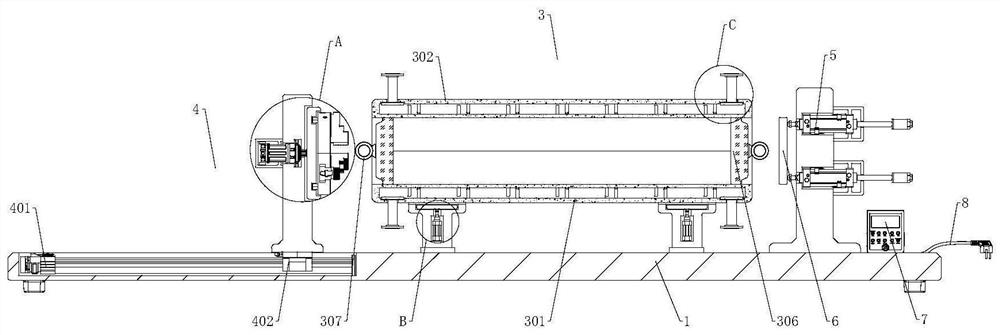
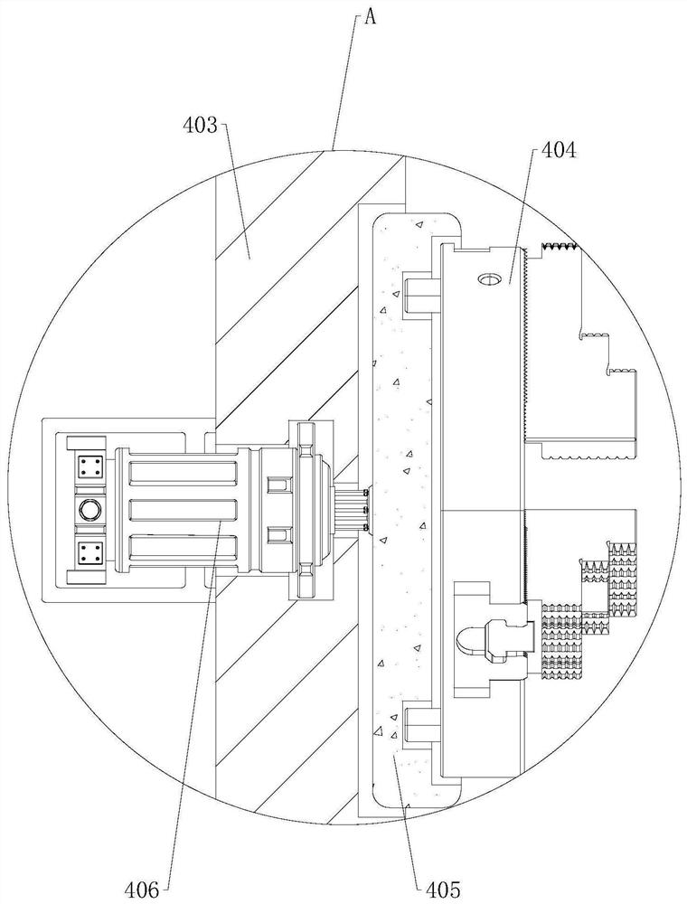
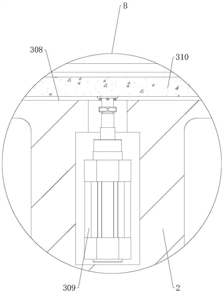
The invention relates to the technical field of alloy casting, in particular to automatic demolding equipment for casting high-temperature alloy bars. The automatic demolding equipment comprises a base, fixing seats are mounted at the two sides of the center of the top of the base, a demolding mechanism is mounted on the tops of the fixing seats, and a traction mechanism is arranged at the top of the base and located at the left side of the demolding mechanism; and a pushing air cylinder is installed at the position, at the right side of the demolding mechanism, of the top of the base, a pushing plate is installed at the left end of the pushing air cylinder, and a control panel is installed at the position, at the right side of the pushing air cylinder, of the top of the base. By arranging the base, the demolding mechanism and the pushing air cylinder, the problem that at present, when high-temperature alloy bars are demolded, the high-temperature alloy bars are generally pushed out of a mold through a hydraulic pushing device, the high-temperature alloy bars can be pushed out only through the hydraulic pushing device with large power due to the fact that the high-temperature alloy bars are tightly connected with the mold, the hydraulic pushing device with large power is high in energy consumption, and the production cost is increased are solved.

Description

technical field [0001] The invention relates to the technical field of alloy casting, in particular to an automatic demoulding equipment for casting superalloy rods. Background technique [0002] The superalloy raw material is smelted in a vacuum induction furnace, cast into a steel pipe mold in a vacuum state, and forms an alloy ingot after cooling. Because the thermal expansion coefficient of the superalloy is smaller than that of ordinary carbon steel and other metals, the process of collecting the solidified ingot is different from that of other metals. difference. [0003] At present, when the high-temperature alloy rod is demoulding, the high-temperature alloy rod is generally pushed out of the mold by using a hydraulic pusher. Since the high-temperature alloy rod is closely connected to the mold, a hydraulic pusher with a large power is required to push out the high-temperature alloy. For rods, the hydraulic propulsion device with higher power consumes more energy, w...

Claims


Application Information

Patent Timeline
Patent Type & Authority Applications(China)
IPC IPC(8): B22D29/06B22D29/08B22D31/00
CPCB22D29/06B22D29/08B22D31/00
Inventor 华忠道
Owner 泰州市锦峰新材料科技有限公司
Learn More