Nut machining device with waste recycling function

A waste recycling and processing device technology, applied in grinding drive devices, metal processing equipment, grinding/polishing safety devices, etc. The effect of secondary utilization, improving work efficiency and avoiding danger

Pending Publication Date: 2022-01-14
惠州市友仁五金制品有限公司
View PDF10 Cites 0 Cited by
  • Summary
  • Abstract
  • Description
  • Claims
  • Application Information

AI Technical Summary

Problems solved by technology

[0003] The surface of the nut needs to be polished during the processing process. The existing grinding device cannot collect the waste material, and the manual recovery of the staff is require

Method used


Image

  • Nut machining device with waste recycling function
  • Nut machining device with waste recycling function
  • Nut machining device with waste recycling function

Examples


Embodiment 1

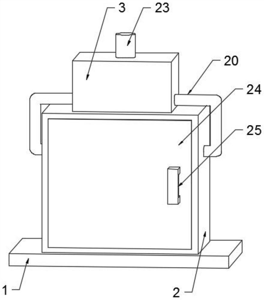
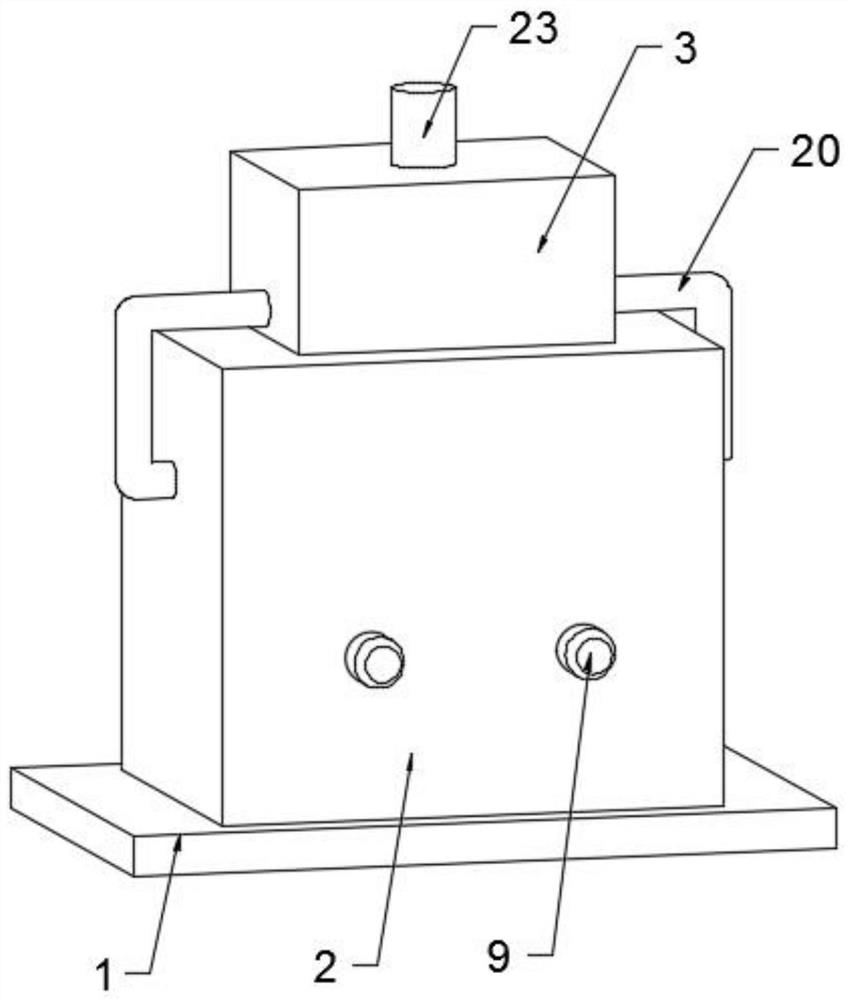
[0030] see Figure 1-Figure 5 , in an embodiment of the present invention, a nut processing device with a waste material recycling function includes a base 1 for supporting and placing a box body 2, the box body 2 fixedly connected to the upper end of the base 1 for supporting and placing a filter box 3, and The filter box 3 fixedly connected to the upper end of the box body 2 is used to support and place the dust suction fan 19, and also includes waste recycling components;

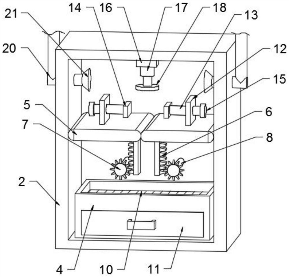
[0031] The waste recycling assembly is used to recycle the waste generated during the grinding process, the waste recycling assembly is fixedly arranged inside the box body 2, the waste recycling assembly includes a recovery box 4, and the recovery box 4 is fixedly connected to the box body 2 On the inner wall of the bottom end of the box body, it is used to support and place the filter plate 10 and the drawer 11. A group of processing plates 5 are hinged on the inner walls of the left and right sides of...

Embodiment 2

[0039] The difference from Embodiment 1 is that: the upper ends of the two groups of processing plates 5 are fixedly connected with a group of fixed plates 12, which are used to support and place threaded rods 13, and the opposite surfaces of the two groups of said fixed plates 12 are rotatably connected with a A group of threaded rods 13 are used to drive the clamping plate 14 to move. The threaded rods 13 of the two groups are all threaded through the fixed plate 12, and are fixedly connected with a rotating block 15, which is convenient for the staff to rotate the threaded rods 13. The threaded rods of the two groups A set of clamping plates 14 are rotatably connected to opposite surfaces of the rod 13 for clamping and fixing the nut.

[0040]The working principle of the present invention is: when in use, utilize the handle 25 to open the box door 24, then rotate two groups of rotating blocks 15, the rotating blocks 15 drive the threaded rods 13 to approach each other, and t...


PUM


Abstract

The invention discloses a nut machining device with a waste recycling function. The nut machining device comprises a base, a box body fixedly connected to the upper end of the base and a filter box fixedly connected to the upper end of the box body. The nut machining device is provided with a waste recycling assembly, and the waste recycling assembly comprises a recycling box fixedly connected to the inner wall of the bottom end of the box body; and the inner walls of the left side and the right side of the box body are each provided with a machining plate in a hinged mode, the lower ends of the two machining plates are each fixedly connected with a rack, one side of each rack is provided with a gear, the racks are meshed with the gears, the back faces of the gears are fixedly connected with rotating shafts, the ends, away from the gears, of the rotating shafts are fixedly connected with the output ends of driving motors, and the driving motors are fixedly installed on the back face of the box body. After nuts are machined, the nuts and waste materials generated in the machining process can be collected and filtered, workers can conveniently conduct secondary utilization on the waste materials, and economy is achieved.

Description

technical field [0001] The invention relates to the technical field of nut processing, in particular to a nut processing device with waste recycling function. Background technique [0002] A nut, also known as a nut, is a fixing tool with a hole in the center and threads on the inside of the hole. Nuts are often shared with matching screws to secure the joints involved. If environmental factors such as vibration cause the nut to loosen, you can use tools such as glue or pins to further strengthen the relevant part. Nuts are mostly hexagonal, followed by squares. A nut is a nut, a part that is screwed together with a bolt or a screw for fastening. It is a component that must be used in all manufacturing machinery. According to different materials, it is divided into carbon Steel, stainless steel, non-ferrous metals (such as copper) and other major types. [0003] The surface of the nut needs to be polished during the processing process. The existing grinding device cannot ...

Claims


Application Information

Patent Timeline
IPC IPC(8): B24B19/00B24B41/06B24B55/12B24B55/06B24B47/00B24B41/00B24B55/00B01D46/10
CPCB24B19/00B24B41/06B24B55/12B24B55/06B24B47/00B24B41/00B24B55/00B01D46/10
Inventor 杨俊奇毛自力岳志发黄继华
Owner 惠州市友仁五金制品有限公司
Why Eureka
Try Eureka