Deep-drilling downhole pushing positioning centering system and method

A centering device and vertical direction technology, applied in earthwork drilling, wellbore/well components, measurement, etc., can solve problems such as high setting pressure, low setting success rate, loss of elasticity, etc., and achieve stable posture, The effect of improving measurement accuracy

Active Publication Date: 2022-01-14
INST OF ROCK & SOIL MECHANICS CHINESE ACAD OF SCI +1
View PDF17 Cites 1 Cited by
  • Summary
  • Abstract
  • Description
  • Claims
  • Application Information

AI Technical Summary

Problems solved by technology

Although this patent realizes the fixing of the equipment in the stage of adoption, there are some deficiencies in actual use: (1) Since the borehole wall of the open hole is very rough and there are many sharp protrusions, even if the length of the packer is increased, the setting The success rate of the test equipment is still low, so that the test equipment is not uniformly stressed, and cannot be positioned and centered in the drilling to maintain posture balance, which will affect the follow-up sampling work; (2) The packer itself is made of rubber-based materials. After going through a downhole operation, most of its elasticity will be lost, and it must be replaced frequently, which increases the cost of the entire device; (3) under deep drilling conditions, the required setting pressure is very high, which will affect the sampling Interference in in-situ stress test results of section borehole wall

Method used


Image

  • Deep-drilling downhole pushing positioning centering system and method
  • Deep-drilling downhole pushing positioning centering system and method
  • Deep-drilling downhole pushing positioning centering system and method

Examples


Embodiment Construction

[0035] In order to make the object, technical solution and advantages of the present invention clearer, the present invention will be further described in detail below in conjunction with the accompanying drawings and embodiments. It should be understood that the specific embodiments described here are only used to explain the present invention, not to limit the present invention. In addition, the technical features involved in the various embodiments of the present invention described below can be combined with each other as long as they do not constitute a conflict with each other.

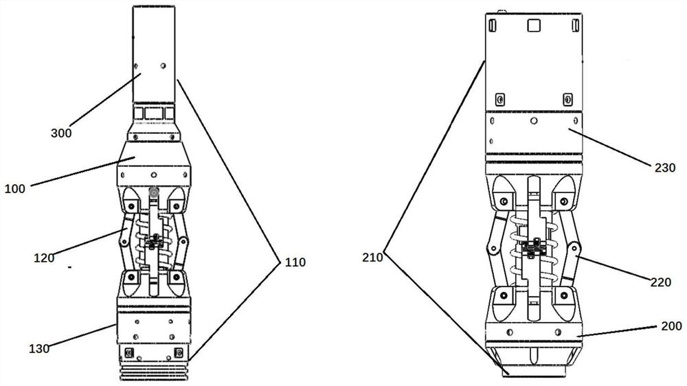
[0036] Such as figure 1 As shown, a deep drilling downhole push positioning and centering system according to an embodiment of the present invention includes a push up positioning centering device 100 and a down pushing positioning centering device 200, both of which are respectively arranged on the upper end of the downhole detection equipment and the centering device 200. At the lower end, th...


PUM


Abstract

The invention discloses a deep-drilling downhole pushing positioning centering system and method. The deep-drilling downhole pushing positioning centering system comprises an upper pushing positioning centering device and a lower pushing positioning centering device which are arranged at the upper end and the lower end of downhole detection equipment correspondingly along the central axis of the downhole detection equipment in the vertical direction, and composition units of the upper pushing positioning centering device and the lower pushing positioning centering device are reversely configured; and within the downhole 3000 meters, reverse thrust is provided through driving units arranged on the upper pushing positioning centering device and the lower pushing positioning centering device through remote control of a control system, thus pushing positioning centering structures arranged on the upper pushing positioning centering device and the lower pushing positioning centering device are unfolded in the single-synchronous radial direction to form supporting points, the downhole detection equipment is fixed and centered in a borehole, and automatic pushing, accurate positioning and intelligent centering operation are achieved. In the sampling stage, the upper pushing positioning centering device and the lower pushing positioning centering device reversely output torque and offset each other, and the situation that the posture of the downhole detection equipment is stable in the sampling process is ensured; and the structure is simple, the deep-drilling downhole pushing positioning centering system is made of a metal material, the intelligent degree is high, the deep-drilling downhole pushing positioning centering system can be reused, the production cost is reduced, and the rock and soil mechanical parameter measuring efficiency is improved.

Description

technical field [0001] The invention belongs to the technical field of on-site measurement equipment for rock and soil mechanics, and more specifically relates to a system and a method for pushing, positioning, and centering in a deep drilling downhole. Background technique [0002] The local wall stress relief method is a new stress relief method. By releasing a sufficient number of cores at the drilling wall and recording the normal strain changes in different directions during the process, the far field stress can be obtained by back calculation. When sampling relevant cores in the well, it is necessary to lower the relevant testing equipment into the well, and then perform sampling after the sampling section is fixed. In order to avoid sloshing of the test equipment in the well during sampling and provide counterforce for the equipment during the stress relief process, a fixed support device is required to fix the equipment on the well wall after it reaches the designate...

Claims


Application Information

Patent Timeline
Patent Type & Authority Applications(China)
IPC IPC(8): E21B47/00E21B49/00
CPCE21B47/00E21B49/00Y02E10/10
Inventor 汤华秦雨樵葛修润吴振君张勇慧袁从华邓琴尹小涛袁晖宋罡刘中敏
Owner INST OF ROCK & SOIL MECHANICS CHINESE ACAD OF SCI
Why Eureka
Try Eureka