Oil casing head under-pressure leaking stoppage system and method

A technology of oil casing and headband, which is applied in the direction of pipeline system, pipe/pipe joint/pipe fitting, pipe element, etc., can solve the problem of grease filling and plugging of the main and auxiliary seals of casing, and the inability to inject grease under pressure in the main and auxiliary seals of casing. , There are no problems such as poor grease injection effect, to achieve the effect of flexible use, work efficiency, and good cementation quality

Pending Publication Date: 2022-01-14
SICHUAN HUAYU PETROLEUM DRILLING & PRODION EQUIP
View PDF9 Cites 0 Cited by
  • Summary
  • Abstract
  • Description
  • Claims
  • Application Information

AI Technical Summary

Problems solved by technology

[0005] The invention provides a pressure plugging system and method for the oil casing head to solve the problem that in the prior art, the main and auxiliary seals of the casing cannot be greased under pressure, and the single use of solid or liquid plugging agents will cause grease injection. The effect is not good and there is currently no special device for grease injection and plugging for the main and auxiliary seals of the casing

Method used


Image

  • Oil casing head under-pressure leaking stoppage system and method
  • Oil casing head under-pressure leaking stoppage system and method
  • Oil casing head under-pressure leaking stoppage system and method

Examples


Embodiment 1

[0034] This embodiment discloses a plugging system with pressure on the casing head, which includes a liquid plugging device and a solid leak plugging device.

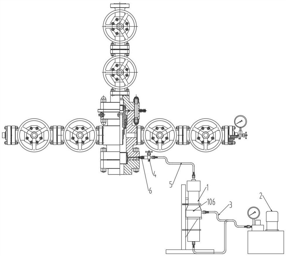
[0035] see Figure 1-2 , The liquid plugging device includes a high-pressure grease injector 1, an explosion-proof hydraulic pump station 2, a hydraulic pipeline 3, a first stop valve 4, and a first grease injection pipeline 5.

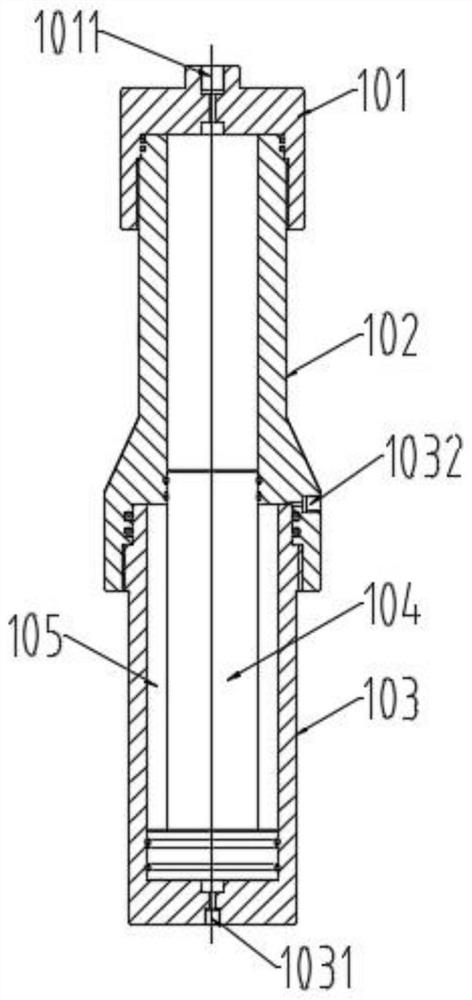
[0036] see figure 2 , the high-pressure grease injector 1 includes a first piston rod 104 and a first cylinder head 101 , an upper cylinder body 102 , and a lower cylinder body 103 which are sequentially threaded on the coaxial line.

[0037] The hollow upper cylinder body 102 and the lower cylinder body 103 form a stroke channel of the first piston rod 104 . Both ends of the first piston rod 104 are respectively sealed and connected to the upper cylinder body 102 and the lower cylinder body 103. Preferably, between the side wall at the top of the first piston rod 104 and the inner wall of ...

Embodiment 2

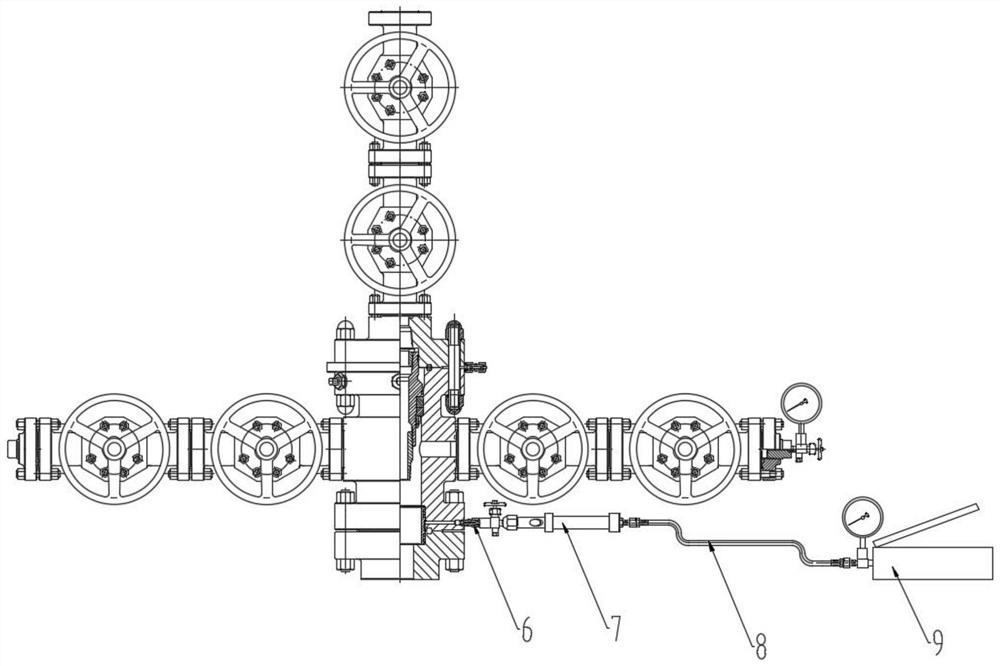
[0046] This embodiment discloses a plugging system with pressure on the casing head. The difference between this embodiment and Embodiment 1 lies in the reciprocating injection molding gun 7 .

[0047] For details, see Figure 6 , the reciprocating injection molding gun 7 in this embodiment includes a second piston rod 703, a rear cylinder cover 705, an oil return joint 712, and a front cylinder cover 701, a first cylinder body 702, a plastic filling cylinder 706, Threaded joint 707, second cut-off valve 708, injection joint 709, grease injection valve nut 710.

[0048] The front cylinder cover 701 is threadedly connected to the first cylinder body 702, and an oil inlet 7011 is opened on the front cylinder cover 701; Plastic tube 706, threaded joint 707, second cut-off valve 708, injection molding joint 709, grease injection valve nut 710 are threaded from head to tail.

[0049] The sidewalls at both ends of the second piston rod 703 are sealed and connected to the inner wal...

Embodiment 3

[0052] This embodiment discloses a leak plugging method with pressure on the oil casing head. The method includes:

[0053] Connect the grease injection valve 6 on the wellhead gate valve with the first shut-off valve 4 .

[0054] Fill the high-pressure grease injector 1 with a liquid leak-stopping agent.

[0055] Open the first cut-off valve 4, start the explosion-proof hydraulic pump station 2, and inject the liquid plugging agent in the high-pressure grease injector 1 into the grease injection valve 6 on the wellhead gate valve; close the first stop valve 4.

[0056] Connect the grease injection valve 6 on the wellhead gate valve with the second cut-off valve 708 .

[0057] Fill the solid plugging agent in the filling cylinder 706 of the reciprocating injection molding gun 7 .

[0058] Open the second shut-off valve 708, pressurize the manual pump 9, inject the solid leakage plugging agent in the reciprocating injection molding gun 7 into the grease injection valve 6 on t...


PUM


Abstract

The invention discloses an oil casing head under-pressure leaking stoppage system and method. The system comprises a liquid leaking stoppage device and a solid leaking stoppage device. The liquid leaking stoppage device comprises a high-pressure grease injector, an anti-explosion hydraulic pump station, a hydraulic pipeline, a first stop valve and a first grease injection pipeline; the high-pressure grease injector is connected with the first stop valve through the first grease injection pipeline; and an oil inlet and an oil outlet are respectively connected to the anti-explosion hydraulic pump station through a first hydraulic pipeline. The solid leaking stoppage device comprises a reciprocating injection gun, a second grease injection pipeline and a manual pump; and the reciprocating injection gun is connected with the manual pump through the second grease injection pipeline. Under-pressure grease injection maintenance work of a wellhead gate valve is carried out under the condition that a wellhead is not closed for pressure relief, and the working efficiency is greatly improved. A liquid leaking stoppage agent or a solid leaking stoppage agent can be selected to be injected firstly according to specific conditions in actual production, and after injection molding is completed, the compressive strength is high, the cementing quality is good, elasticity is achieved, permeability is avoided, and the shrinkage rate is small after curing.

Description

technical field [0001] The invention relates to the technical field of pressurized rectification of oil and casing heads in the petroleum and natural gas industry, and in particular to a system and method for oil and casing heads with pressure for leak plugging. Background technique [0002] In the on-site maintenance and repair work of the wellhead tubing and casing head, the primary and secondary seals of the casing will fail due to aging factors. The cost of conventional well killing methods is too high, and there is a very high safety risk. [0003] When the sealing part is seriously damaged, if the liquid plugging agent is injected, it will cause leakage before solidification, and if the solid plugging agent is injected, there will be local gaps, and the compressive strength and cementation quality will not be high. [0004] At present, there is no special device for grease injection plugging for the primary and secondary seals of the casing. Contents of the invention...

Claims


Application Information

Patent Timeline
Patent Type & Authority Applications(China)
IPC IPC(8): F16L55/175F16L55/18F16K51/00F17D1/14F17D3/01F04B15/02
CPCF16L55/175F16L55/18F16K51/00F17D1/14F17D3/01F04B15/02
Inventor 何磊杨太刚李俊姚榆杨天佑敖昌林
Owner SICHUAN HUAYU PETROLEUM DRILLING & PRODION EQUIP
Why Eureka
Try Eureka