
Radio frequency electronic component testing device and testing equipment applying same

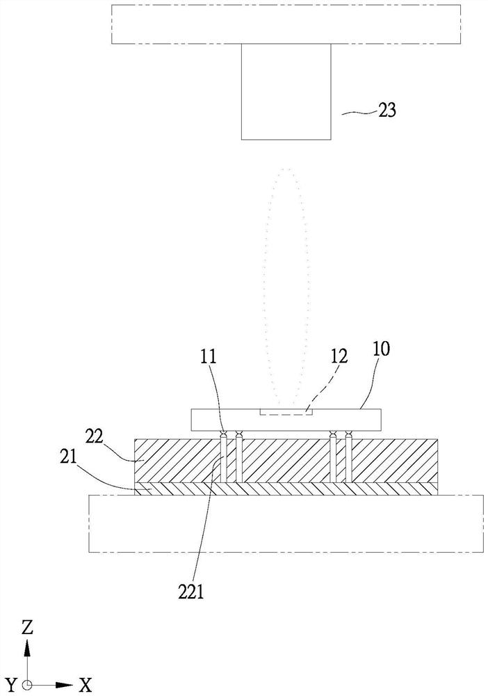
A technology for electronic components and testing devices, which is applied in the directions of measuring devices, measuring device casings, shielding devices, etc., can solve the problems of contact between contacts 11 and probes 221, affecting the electrical test quality of radio frequency electronic components 10, etc., so as to improve the test quality effect

Pending Publication Date: 2022-01-18
HON PRECISION INC
View PDF0 Cites 3 Cited by
  • Summary
  • Abstract
  • Description
  • Claims
  • Application Information

AI Technical Summary

Problems solved by technology

[0005] Furthermore, the above-mentioned radio frequency electronic component 10 only uses the pressure of its own weight to make the contact 11 contact the probe 221 of the test socket 22. Since the probe 221 has a spring inside, this self-weight pressure cannot make the contact 11 and the probe 221 contact each other. , so as to affect the electrical test quality of the radio frequency electronic component 10; because the antenna 12 of the radio frequency electronic component 10 is relative to the antenna tester 23, how to transmit wireless signals between the antenna tester 23 and the radio frequency electronic component 10 can be Crimping RF electronic components 10 to perform electrical testing operations is also the target of industry research and development

Method used


Image

  • Radio frequency electronic component testing device and testing equipment applying same
  • Radio frequency electronic component testing device and testing equipment applying same
  • Radio frequency electronic component testing device and testing equipment applying same

Examples


no. 1 example

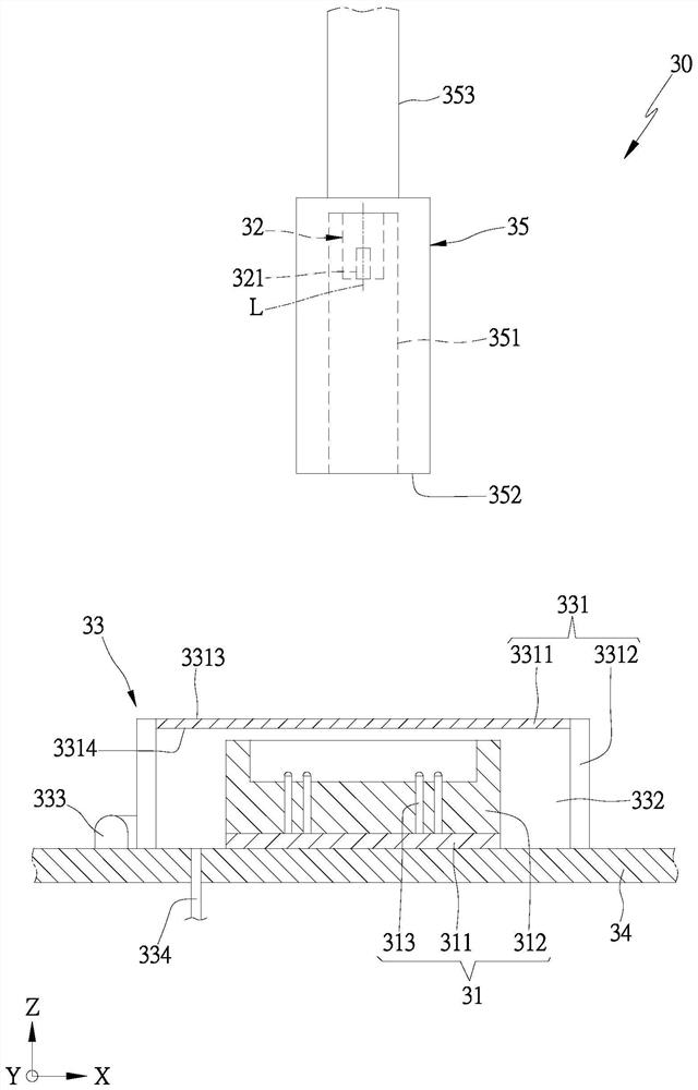
[0043] see figure 2 , the first embodiment of the testing device 30 of the present invention includes an electrical tester 31 , an antenna tester 32 and a test chamber 33 .

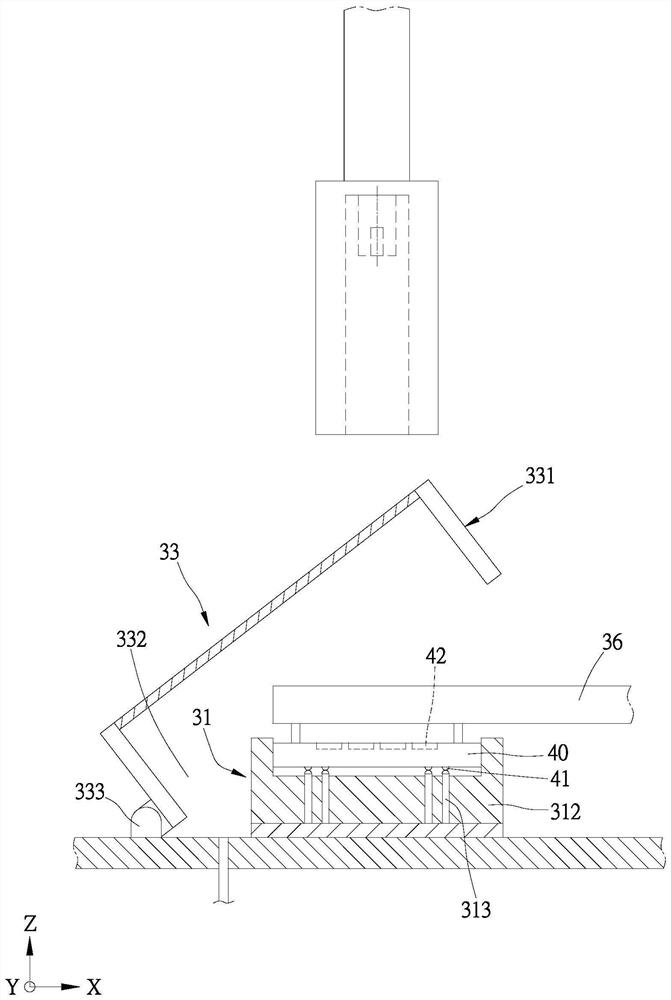
[0044] The electrical tester 31 is provided with an electrically connected circuit board 311 and at least one test socket 312, and the test socket 312 is electrically connected to the radio frequency electronic components at the test station to perform electrical testing operations on the radio frequency electronic components; further, The test socket 312 has a plurality of branch probes 313 , one end of the probes 313 is electrically connected to the circuit board 311 , and the other end is electrically connected to the radio frequency electronic components. Furthermore, the test station is the position where the radio frequency electronic components are preset to perform the test operation. For example, the test station can be located on the electrical tester 31 or the carrier, etc., depending on the r...


PUM


Abstract

The invention provides a radio frequency electronic component testing device which comprises an electrical tester, an antenna tester and a testing chamber, wherein the testing chamber is provided with a cover body with a first anti-interference component, the first anti-interference component is made of shielding-proof materials and has a low dielectric coefficient so that wireless signals can pass through, the cover body closes a first bearing tool to form a testing space, and the testing space is used for accommodating an electrical tester with a radio frequency electronic component; the testing chamber is located between the electrical tester and the antenna tester, so that the radio frequency electronic component can execute electrical testing operation in the electrical tester in the testing chamber, and can also execute wireless signal testing operation with the external antenna tester through the first anti-interference component in the testing chamber, thereby improving the testing quality. The invention further provides testing equipment applying the radio frequency electronic component testing device. The testing equipment comprises a machine table, a feeding device, a material receiving device, a radio frequency electronic component testing device, a conveying device, and a central control device.

Description

technical field [0001] The invention provides a radio frequency electronic component testing device and testing equipment using the same, which relates to a test room located between an electrical tester and an antenna tester, which not only makes the radio frequency electronic components in the test room inside the preset test environment The electrical tester performs electrical test operations, and can also conduct wireless signal test operations with the external antenna tester through the first anti-interference component of the test room, thereby improving the test quality of the test device. Background technique [0002] see figure 1 , a radio frequency electronic component 10 with multiple antennas built in is widely used in fields such as mobile communication area wireless network systems and wireless communication area network systems; currently the radio frequency electronic component 10 is provided with a plurality of contacts 11 on one side, and on the other sid...

Claims


Application Information

Patent Timeline
Patent Type & Authority Applications(China)
IPC IPC(8): G01R31/00G01R29/10G01R1/04G01R1/18
CPCG01R31/00G01R29/10G01R1/0408G01R1/18
Inventor 李子玮
Owner HON PRECISION INC
Learn More