Check patentability & draft patents in minutes with Patsnap Eureka AI!

Automatic wafer positioning assembly

A technology for positioning assemblies and wafers, applied in electrical components, semiconductor/solid-state device manufacturing, circuits, etc., and can solve the problems of radial wafer movement, wafer slippage, uneven airflow distribution, etc.

Pending Publication Date: 2022-01-18
GRAND PLASTIC TECH
View PDF0 Cites 0 Cited by
  • Summary
  • Abstract
  • Description
  • Claims
  • Application Information

AI Technical Summary

Problems solved by technology

[0004] Since the airflow introduced between the bottom of the wafer and the Bernoulli turntable may generate uneven airflow distribution in an instant, the wafer rotating at high speed at this time may move radially due to the uneven airflow distribution, and then deviate from the Wafer slippage may occur at the center of the Bernoulli turntable, seriously affecting the progress of subsequent processes
[0005] In view of this, how to provide an automatic wafer positioning assembly to perform positioning during wafer rotation, to avoid radial movement of high-speed rotating wafers due to uneven air distribution, thereby deviating from the center point of the Bernoulli turntable or The phenomenon of wafer slippage is an urgent problem in this industry

Method used


Image

  • Automatic wafer positioning assembly
  • Automatic wafer positioning assembly
  • Automatic wafer positioning assembly

Examples


Embodiment Construction

[0031] In order to make the above and other objectives, features, and advantages of the present disclosure more comprehensible, preferred embodiments of the present disclosure will be exemplified below in detail with reference to the attached drawings. Furthermore, the direction terms mentioned in this disclosure, such as up, down, top, bottom, front, back, left, right, inside, outside, side layer, surrounding, center, horizontal, transverse, vertical, longitudinal, axial , radial direction, the uppermost layer or the lowermost layer, etc., are only directions for referring to the attached drawings. Therefore, the directional terms used are used to explain and understand the present disclosure, but not to limit the present disclosure.

[0032] In the figures, structurally similar units are denoted by the same reference numerals.

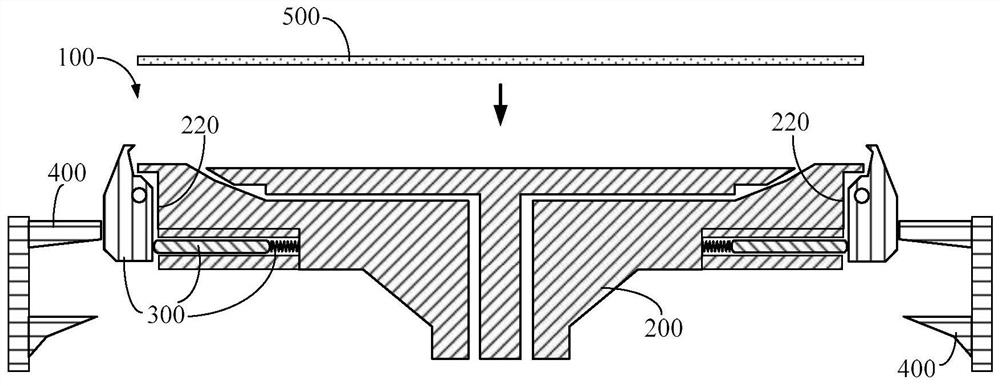
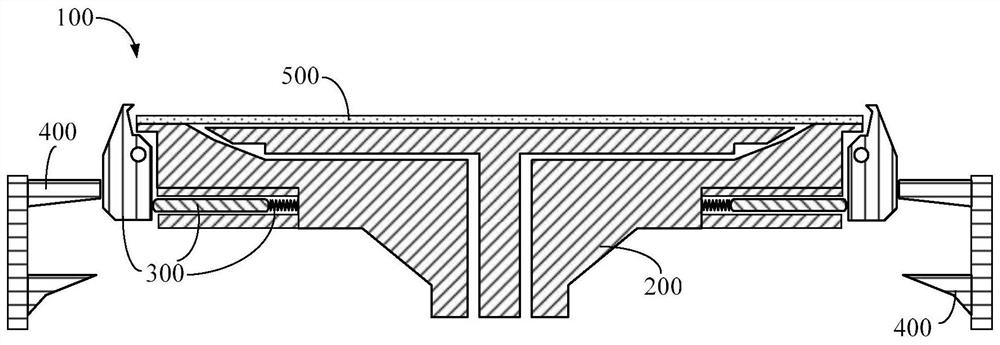
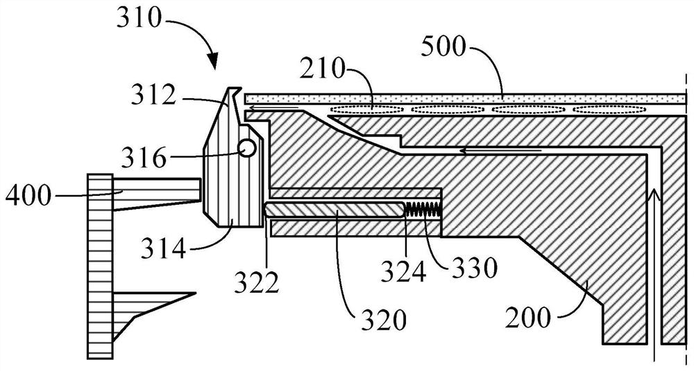
[0033] This disclosure relates to an automatic wafer positioning assembly, which can be used to position the wafer when it is suspended and rotated...


PUM


Abstract

The invention provides an automatic wafer positioning assembly which is used for positioning a wafer for wet processing. The automatic wafer positioning assembly comprises a Bernoulli rotary disc, a plurality of positioning devices and a control part. When the Bernoulli rotary disc does not generate the air cushion and the control part enables the plurality of positioning devices to be in an open state, the wafer can be placed on the Bernoulli rotary disc or taken out from the Bernoulli rotary disc. When the Bernoulli rotary disc generates an air cushion and the control part enables the plurality of positioning devices to be in a closed state, the wafer is suspended and rotated above the Bernoulli rotary disc for wet processing.

Description

【Technical field】 [0001] The disclosure relates to a positioning assembly, in particular to an automatic wafer positioning assembly. 【Background technique】 [0002] In the prior art, when it is desired to carry out wet processes such as etching and cleaning for thinned or warped wafers, in the case where a vacuum suction turntable cannot be used for processing, in order to prevent spraying on the processing surface of the wafer (such as : upward) the chemical solution overflows to the protective surface of the wafer (for example: downward), and the processing purposes such as etching and cleaning will be achieved by using a Bernoulli Chuck. [0003] Bernoulli's Principle, which is used in Bernoulli's turntable, its establishment mechanism is to place the wafer above the Bernoulli turntable, and then introduce airflow between the bottom of the wafer and the Bernoulli turntable to form Air cushion and create negative pressure at the same time. At this time, through proper ai...

Claims


Application Information

Patent Timeline
Patent Type & Authority Applications(China)
IPC IPC(8): H01L21/68
CPCH01L21/68
Inventor 邱云正
Owner GRAND PLASTIC TECH
Features
  • R&D
  • Intellectual Property
  • Life Sciences
  • Materials
  • Tech Scout
  • Unparalleled Data Quality
  • Higher Quality Content
  • 60% Fewer Hallucinations
Learn More