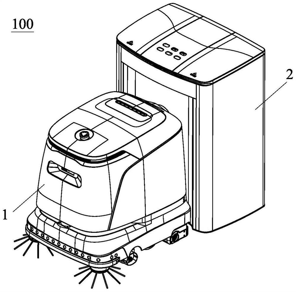
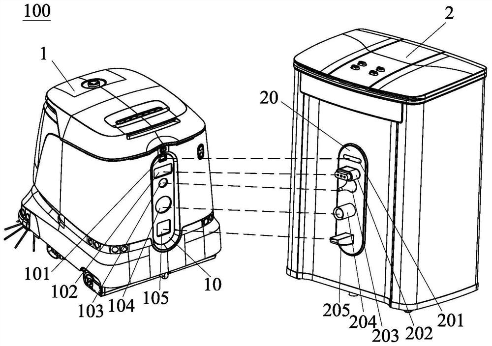
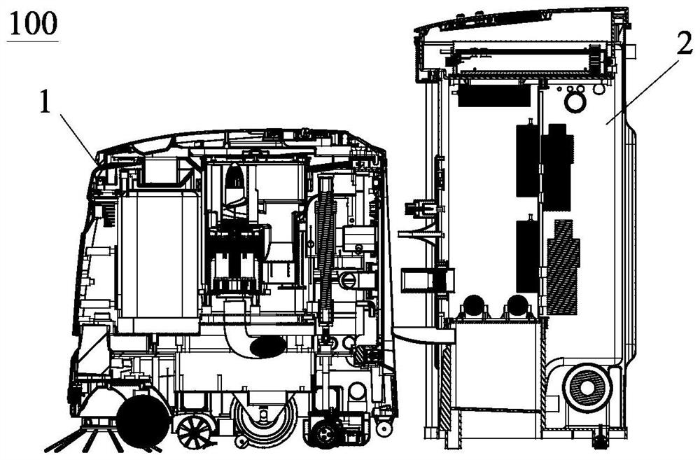
Cleaning robot and system

A technology for cleaning robots and clear water, applied in the field of robots, can solve problems such as unhygienic, time-consuming and labor-intensive, and user replacement errors

Pending Publication Date: 2022-01-21
浙江齐元机器人有限公司
View PDF8 Cites 1 Cited by
  • Summary
  • Abstract
  • Description
  • Claims
  • Application Information

AI Technical Summary

Problems solved by technology

It can be seen that the existing cleaning robot can only realize the function of vacuuming or mopping the floor during cleaning work, and cannot realize two cleaning functions at the same time, and the cleaning function is single
Moreover, when implementing different functions, users need to replace many accessories, and users are prone to make replacement mistakes or forget to replace them, which will cause the cleaning robot to malfunction and fail to work, and make the assembly process of the intelligent cleaning robot difficult and costly.
[0005](2) The existing cleaning robot sets a rag at the bottom to mop the floor during walking. After mopping the floor for a long time, water and dirt Attached to the rag, it may cause secondary pollution to the ground during the subsequent floor cleaning process. The rag needs to be disassembled by the user for manual cleaning, which is time-consuming, laborious, unhygienic and affects the user experience.
Since the fan must rotate at high speed to generate sufficient vacuum, the temperature of the fan rotor will be high (up to 100°C) after long-term operation, and the airflow passing through the fan will also become hot airflow, which will cause the indoor temperature to drop if it is directly discharged into the environment. Elevated, not well recycled

Method used


Image

  • Cleaning robot and system
  • Cleaning robot and system
  • Cleaning robot and system

Examples


Embodiment Construction

[0058] The following will clearly and completely describe the technical solutions in the embodiments of the present invention with reference to the accompanying drawings in the embodiments of the present invention. Obviously, the described embodiments are only some, not all, embodiments of the present invention. Based on the embodiments of the present invention, all other embodiments obtained by persons of ordinary skill in the art without creative efforts fall within the protection scope of the present invention.

[0059] In describing the present invention, it should be understood that the terms "center", "longitudinal", "transverse", "length", "width", "thickness", "upper", "lower", "front", " Orientation indicated by rear, left, right, vertical, horizontal, top, bottom, inside, outside, clockwise, counterclockwise, etc. The positional relationship is based on the orientation or positional relationship shown in the drawings, which is only for the convenience of describing t...


PUM


Abstract

A cleaning robot comprises a dust collecting box, a clean water tank, a sewage tank, a rolling brush assembly and a rolling mop assembly, the clean water outlet of the clean water tank is connected with the water adding opening of the rolling mop assembly through a clean water outlet pipe, a clean water pump is arranged on the clean water outlet pipe, and clean water in the clean water tank flows into a rolling mop of the rolling mop assembly under the action of the clean water pump to be used for mopping the floor and cleaning the rolling mop; the sewage inlet of the sewage tank is connected with the sewage outlet of the rolling mop assembly through a sewage inlet pipe, a first sewage pump is arranged on the sewage inlet pipe, and sewage generated after the rolling mop assembly cleans, rolls and mops enters the sewage tank under the action of the first sewage pump; and the dust inlet of the dust collecting box is connected with the dust collecting opening of the rolling brush assembly through a dust suction pipe, the air outlet of the dust collecting box is connected with the air inlet of the rolling mop assembly through an air outlet pipe, a first draught fan is arranged in the dust collecting box, dust and garbage raised by the rolling brush assembly through a rolling brush are sucked into the dust collecting box through the dust suction pipe, and hot air passing through the first fan is blown into the rolling mop assembly through the air outlet pipe so as to dry the mopped ground.

Description

technical field [0001] The invention relates to the field of robots, in particular to a cleaning robot and a cleaning robot system. Background technique [0002] The functions of the cleaning robots on the existing market are relatively simple, and they mainly perform cleaning tasks such as vacuuming and sweeping. As users rely on the use of cleaning robots, cleaning robots with functions such as washing and mopping the floor have gradually appeared. , mainly by setting a dust box inside the cleaning robot to collect dust and garbage, or setting a water tank for mopping and washing the floor. [0003] But, the inventor finds when implementing the present invention, existing cleaning robot has following technical problem at least: [0004] (1) The interior of the existing cleaning robot is equipped with an independent dust box or water tank, and the bottom of the cleaning robot is equipped with independent cleaning parts to perform cleaning tasks. The user can perform the re...

Claims


Application Information

Patent Timeline
Patent Type & Authority Applications(China)
IPC IPC(8): A47L11/24A47L11/30A47L11/40F26B21/00
CPCA47L11/24A47L11/302A47L11/4041A47L11/4094A47L11/4083A47L11/4016A47L11/4091A47L11/40F26B21/004A47L2201/00A47L2201/02
Inventor 许治纲陈毅
Owner 浙江齐元机器人有限公司
Why Eureka
Try Eureka