Casting machine mold locking mechanism applied to new energy

A locking mechanism and casting machine technology, applied in the direction of manufacturing tools, casting molding equipment, mold boxes, etc., can solve problems such as troublesome and unsatisfactory sealing effect, reduce friction, enhance sealing effect, and ensure gas dense effect

Pending Publication Date: 2022-01-21
安徽迪川机械设备维修有限公司
View PDF0 Cites 0 Cited by
  • Summary
  • Abstract
  • Description
  • Claims
  • Application Information

AI Technical Summary

Problems solved by technology

[0002] With the development and utilization of new energy, the existing non-renewable energy has been greatly saved, and at the same time it has also played a role in protecting the environment, especially in the field of new energy vehicles, reducing carbon dioxide emissions. The protection of the environment has been increased, and in the field of machinery for new energy applications, it is also necessary to produce various machinery, including casting machine molds. When casting machine molds are used, they need to be locked , the conventional locking method uses bolts and screws to fix, which is very troublesome, and there are still gaps after locking, which makes the sealing effect not ideal

Method used


Image

  • Casting machine mold locking mechanism applied to new energy
  • Casting machine mold locking mechanism applied to new energy
  • Casting machine mold locking mechanism applied to new energy

Examples


Embodiment 1

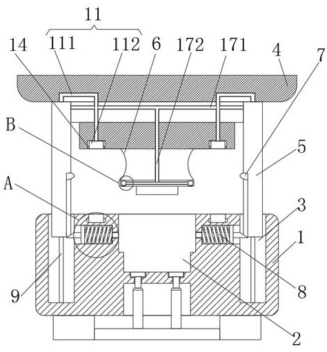
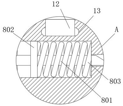
[0035] see figure 1 , figure 2 , Figure 4 and Figure 6 , the mold locking mechanism of the casting machine applied to new energy, including the lower mold base 1 and the upper mold base 4, the inside of the lower mold base 1 is provided with a cavity 2, and the two sides of the top of the lower mold base 1 are provided with limiting holes 3 , the inside of the lower mold base 1 is provided with a locking assembly 8, the top of the upper mold base 4 is fixedly installed with a hydraulic column, the bottom of the upper mold base 4 is fixedly connected with the limit cylinder 5, and the bottom of the upper mold base 4 is fixedly connected with a punch 6. The side of the limiting cylinder 5 is fixedly connected with the protrusion 7, and the locking assembly 8 includes a fixed rod 801 movably connected inside the lower mold base 1, a fixed block 802 fixedly connected on the surface of the fixed rod 801, and a fixed block fixedly connected to the fixed block. Spring 803 on 80...

Embodiment 2

[0039] see figure 1 , Figure 5 and Figure 8 , the inner wall of the limit hole 3 is fixedly connected with the limit rod 9, the top of the limit rod 9 is fixedly connected with the limit block 10, the side of the limit block 10 is movably connected with the inner wall of the limit cylinder 5, and the inside of the upper die base 4 is set There is a sealing assembly 11, and the sealing assembly 11 includes an air duct 111 fixedly connected to the top of the limit cylinder 5 and a rubber air cushion 112 fixedly connected to one end of the air duct 111, and a sealing cavity 12 is opened on the top of the lower mold base 1,

[0040] The side of the rubber air cushion 112 is fixedly connected with a rubber block 14, and the inner wall of the sealing chamber 12 is provided with an arc groove 13. The top view surfaces of the rubber air cushion 112 and the sealing chamber 12 are designed to be ring-shaped, and the rubber air cushion 112 enters into the sealing chamber 12 after moving...

Embodiment 3

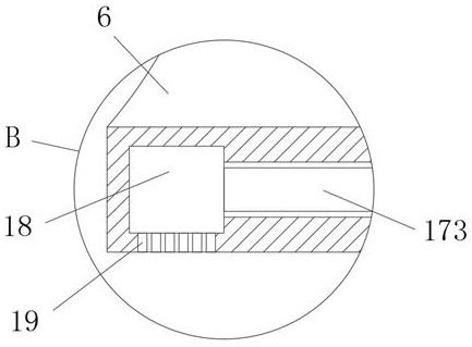
[0043] see figure 1 , image 3 , Figure 5 and Figure 7 , the inside of the limiting cylinder 5 is provided with an air bag 15, the side wall of the limiting cylinder 5 is provided with a through hole 16, the through hole 16 communicates with the air bag 15 through a catheter, the top of the through hole 16 is fixedly connected with a connecting assembly 17, and the upper mold The inside of the seat 4 is provided with a cavity 18, and the bottom of the cavity 18 is provided with an air outlet 19. The connecting assembly 17 includes a first connecting pipe 171 fixedly connected to the side wall of the limit cylinder 5, a first connecting pipe 171 fixedly connected to the first connecting pipe 171 The vertical pipe 172 at the bottom is fixedly connected to the second connecting pipe 173 at the bottom of the vertical pipe 172 , and one end of the second connecting pipe 173 communicates with the interior of the cavity 18 .

[0044] The difference from Example 2 is that the coo...


PUM


Abstract

The invention relates to the technical field of new energy casting, and particularly discloses a casting machine mold locking mechanism applied to new energy. The casting machine mold locking mechanism comprises a lower mold base and an upper mold base, a cavity is formed inside the lower mold base, limiting holes are formed in the two sides of the top of the lower mold base, a locking assembly is arranged inside the lower mold base, a hydraulic column is fixedly installed on the top of the upper mold base, a limiting cylinder is fixedly connected to the bottom of the upper mold base, and a male mold is fixedly connected to the bottom of the upper mold base. A limiting barrel is arranged on the upper mold base, meanwhile, the limiting barrel is matched with a limiting hole formed in the lower mold base, the upper mold base and the lower mold base can be limited and fixed, the stability of the upper mold base is guaranteed when the upper mold base is moved, a protruding block is arranged on the side face of the limiting barrel, the locking assembly can be smoothly pushed away by the protruding block, the male mold is clamped by a fixing rod on the locking assembly, so that the locking effect on the male mold is achieved, and the stability of fixation between the upper mold base and the lower mold base is guaranteed.

Description

technical field [0001] The invention relates to the technical field of new energy casting, in particular to a casting machine mold locking mechanism applied to new energy. Background technique [0002] With the development and utilization of new energy, the existing non-renewable energy has been greatly saved, and at the same time, it has also played a role in protecting the environment, especially in the field of new energy vehicles, reducing carbon dioxide emissions. The protection of the environment has been increased, and in the field of machinery for new energy applications, it is also necessary to produce various machinery, including casting machine molds. When casting machine molds are used, they need to be locked , The conventional locking method uses bolts and screws to fix, which is very troublesome, and there are still gaps after locking, which makes the sealing effect not ideal. Contents of the invention [0003] Aiming at the deficiencies of the prior art, th...

Claims


Application Information

Patent Timeline
IPC IPC(8): B22C21/08
CPCB22C21/08
Inventor 孙言山
Owner 安徽迪川机械设备维修有限公司
Why Eureka
Try Eureka