Surface layer tin plating equipment for copper wire treatment

A technology of tinning equipment and surface layer, which is applied in the field of surface tinning equipment for copper wire processing, and can solve the problems of cumbersome operation and low work efficiency

Pending Publication Date: 2022-01-21
江西腾江铜业有限公司
View PDF0 Cites 0 Cited by
  • Summary
  • Abstract
  • Description
  • Claims
  • Application Information

AI Technical Summary

Problems solved by technology

[0004] In order to overcome the shortcomings of cumbersome operation and low work efficiency caused by separate processing of multiple processes in traditional equipm

Method used


Image

  • Surface layer tin plating equipment for copper wire treatment
  • Surface layer tin plating equipment for copper wire treatment
  • Surface layer tin plating equipment for copper wire treatment

Examples


Embodiment 1

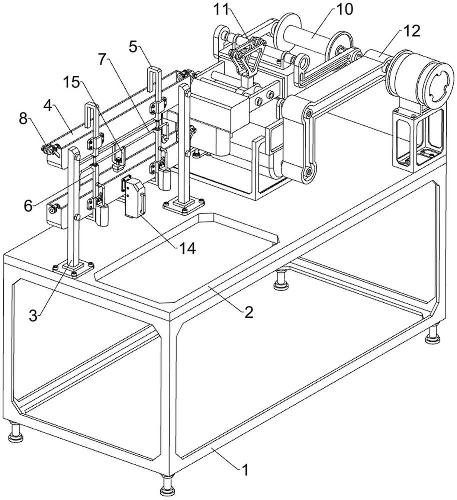
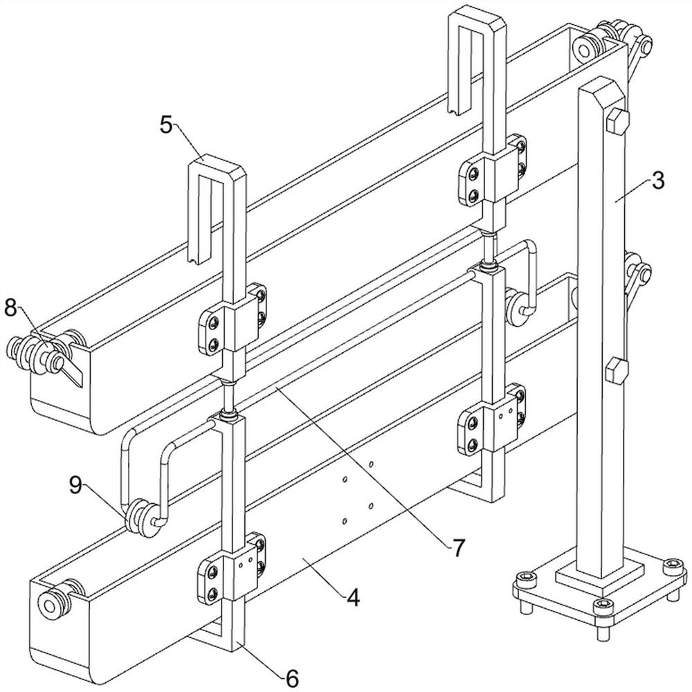
[0036] A surface tinning equipment for copper wire processing, such as Figure 1-10As shown, it includes a bracket 1, a backing plate 2, a supporting plate 3, a processing frame 4, a pressing plate 5, a moving plate 6, a frame rod 7, a first fixed pulley 8, a second fixed pulley 9, a winding assembly 10, and an adjustment assembly 11 and drive assembly 12, the backing plate 2 is welded on the top of the bracket 1, the left and right sides of the left rear side of the backing plate 2 are fixed with support plates 3 by bolts, and the upper and lower parts between the left and right support plates 3 are fixed by bolts. The processing frame 4 is connected, and the left and right sides of the processing frame 4 are provided with guide cylinders, which are used to guide the copper wire. line, the lower processing frame 4 is slidingly provided with a moving plate 6, the bottom of the pressing plate 5 is connected to the top of the moving plate 6, the upper part of the moving plate 6 ...

Embodiment 2

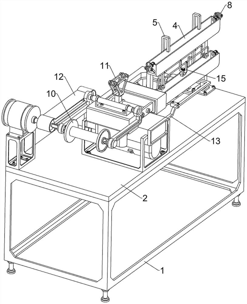
[0043] On the basis of Example 1, such as figure 1 , figure 2 , Figure 11 , Figure 12 , Figure 13 , Figure 14 , Figure 15 and Figure 16 As shown, it also includes a pressing assembly 13. The pressing assembly 13 includes a vertical plate 131, a second push rod 132, a strip plate 133 and a horizontal plate 134. The lower rear side of the protective shell 102 is welded with a vertical plate 131. On the plate 131, the rotation type is provided with a second push rod 132, the second push rod 132 is connected with the rear side of the rotating rod 124 of the bottom, and the lower right part of the moving plate 6 is fixedly connected with a strip plate 133 by bolts, and the right side of the strip plate 133 is provided with a strip plate 133. There is a horizontal plate 134 , and the second push rod 132 rotates and contacts with the horizontal plate 134 .

[0044] Also includes a fixed assembly 14, the fixed assembly 14 includes an arc-shaped shell 141, a second slidin...


PUM


Abstract

The invention relates to tin plating equipment, in particular to surface layer tin plating equipment for copper wire treatment. The surface layer tin plating equipment for copper wire treatment integrates multiple functions, and is easy to operate and high in working efficiency. The surface layer tin plating equipment for copper wire treatment comprises a support, a base plate, supporting plates, treatment frames, pressing plates, movable plates and a frame rods, the base plate is arranged at the top of the support, the supporting plates are arranged on the left side and the right side of the left rear side of the base plate, the treatment frames are arranged on the upper portion and the lower portion between the left supporting plate and the right supporting plate, and the pressing plates are slidably arranged on the left side and the right side of the treatment frame on the upper portion; and the movable plates are slidably arranged on the lower treatment frame, the bottoms of the pressing plates are connected with the tops of the movable plates, and the frame rod is arranged on the upper portions of the movable plates. A copper wire is firstly subjected to acid pickling through the lower treatment frame so as to ensure that a tin layer and the copper wire have good adhesiveness; then the copper wire is subjected to tin plating through the upper treatment frame; and after tin plating is completed, the tinned copper wire is wound by rotating a winding reel, and the purpose of integrating multiple functions is achieved.

Description

technical field [0001] The invention relates to tinning equipment, in particular to surface tinning equipment for copper wire processing. Background technique [0002] In order to prevent the copper wire from being oxidized when exposed to the air, thereby affecting the conductivity of the copper wire, when the copper wire is processed, a layer of tin is plated on the surface of the copper wire to improve the conductivity of the copper wire. At present, when tinning copper wires, it is necessary to process the copper wires step by step through multiple processes, which in turn need to be pickled, tinned and then drawn, while the traditional multiple processes of equipment are generally processed separately , It takes a lot of time and manpower, and the operation is cumbersome, resulting in low work efficiency and inconvenient for people to use. [0003] Therefore, it is necessary to invent a kind of multifunctional integrated type, simple to operate, and the surface layer t...

Claims


Application Information

Patent Timeline
IPC IPC(8): C23G3/02C25D3/30C25D5/34
CPCC23G3/021C23G3/025C25D3/30C25D5/34
Inventor 游选波汪育民
Owner 江西腾江铜业有限公司
Why Eureka
Try Eureka