
Surface drying device used during copper wire tinning

A technology for surface drying and tinning of copper wires, applied in heating devices, progressive dryers, drying solid materials, etc., can solve the problems affecting the working efficiency of the tinning process and the tin liquid is easy to remain on the surface of copper wires, etc., to achieve reduction Effects of waiting time, preventing bending, and improving work efficiency

Active Publication Date: 2022-01-21
江西宏荣金属制品有限公司
View PDF12 Cites 0 Cited by
  • Summary
  • Abstract
  • Description
  • Claims
  • Application Information

AI Technical Summary

Problems solved by technology

[0003] Now, when tinning the copper wire, it is necessary to put the copper wire into the tin solution. After the tinning, the surface of the copper wire tends to remain with the tin solution. As a result, people need to air-dry it before storing it. Due to the normal air-drying It needs to wait for a long time, which is easy to affect the work efficiency of the whole tinning process. Therefore, in view of the above situation, it is necessary to design a surface drying device for copper wire tinning that can reduce the waiting time for air drying.

Method used


Image

  • Surface drying device used during copper wire tinning
  • Surface drying device used during copper wire tinning
  • Surface drying device used during copper wire tinning

Examples


Embodiment 1

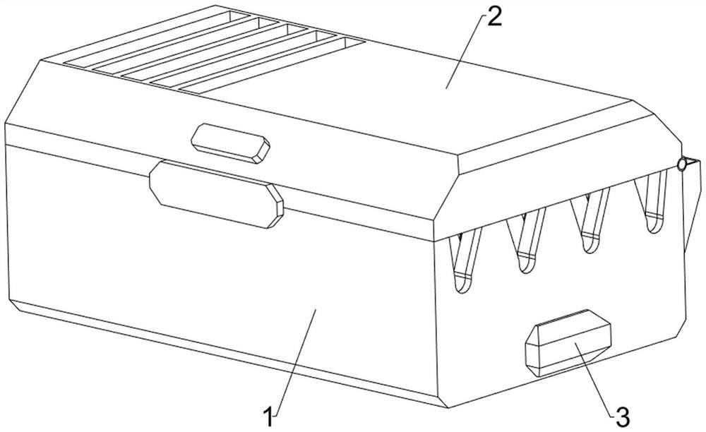
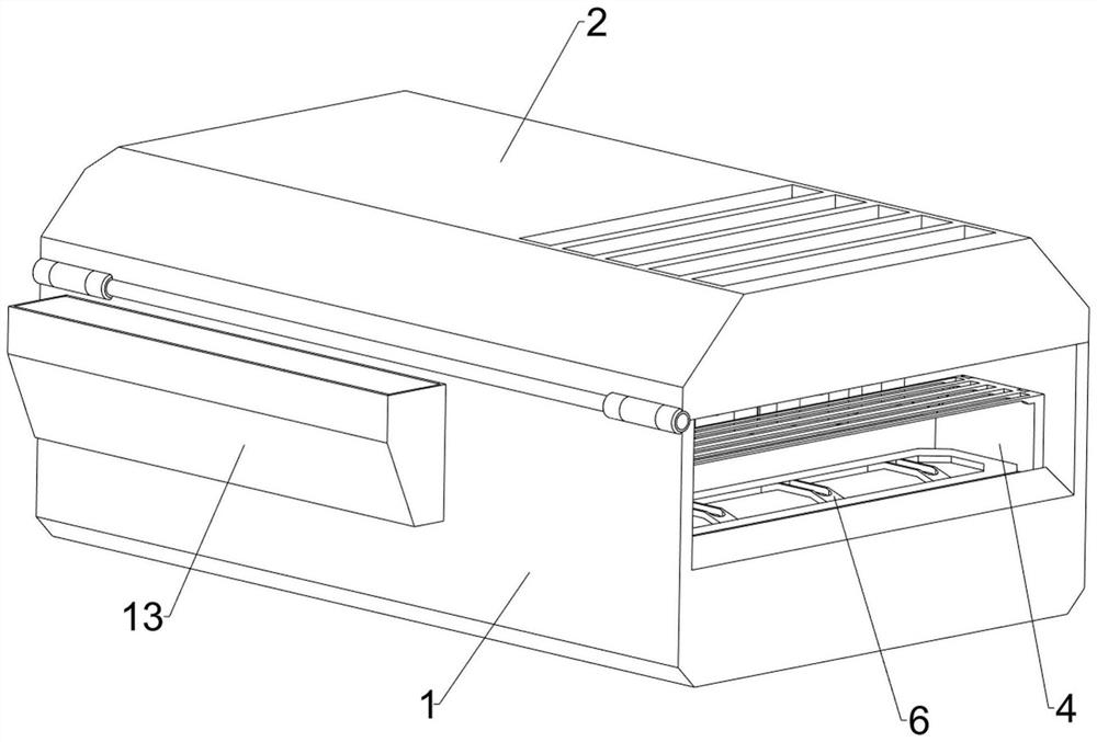
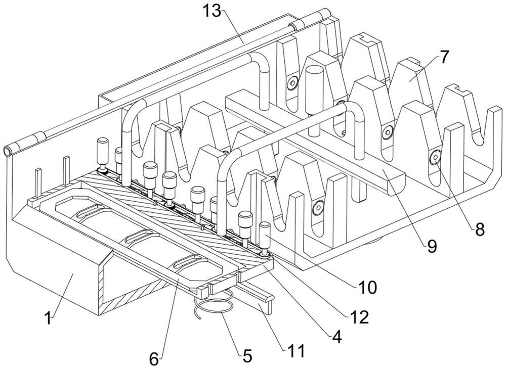
[0038] A surface drying device for copper wire tinning, such as Figure 1-Figure 10 As shown, it includes a working box 1, a cover 2, a connecting frame 4, a first spring 5, a heating plate 6, a tinning component 7, an auxiliary fixing component 8, a pressing component 9 and an adjusting component 10, and the rear side of the top of the working box 1 The rotating type is provided with a cover 2, and the sliding type is provided with a connecting frame 4 on the upper left side inside the working box 1. There are two first springs 5 ​​between the bottom of the connecting frame 4 and the working box 1. There is a heating device on the left side of the connecting frame 4. Plate 6, after heating plate 6 starts working, can heat the copper wire after tinning, work box 1 inner upper side is provided with tinning assembly 7, copper wire is placed on the tinning assembly 7, tinning assembly 7 can Tinning the copper wire, the tinning assembly 7 is provided with an auxiliary fixing assem...

Embodiment 2

[0045] On the basis of Example 1, such as figure 2 , image 3 , Figure 11 , Figure 12 , Figure 13 , Figure 14 with Figure 15 As shown, a wire take-up assembly 11 is also included, and the wire take-up assembly 11 includes a distance sensor 1101, a drive motor 1102, a transmission wheel 1103 and a belt 1104, and a distance sensor 1101 is arranged at the left middle part of the inner bottom of the working box 1, and the inside of the connecting frame 4 The lower part of the rear side is provided with a driving motor 1102. After the driving motor 1102 starts to work, it can drive the auxiliary roller 101 to rotate. The output shaft of the driving motor 1102 is provided with a drive wheel on the lower side of the second connecting rod 102 which is not adjacent to four of them. 1103 , a belt 1104 is wound between the transmission wheels 1103 .

[0046] Also includes a limiting assembly 12, the limiting assembly 12 includes a T-shaped limiting rod 1201, a clamping rod 12...


PUM


Abstract

The invention relates to a drying device, in particular to a surface drying device used during copper wire tinning. The technical problem is to provide a surface drying device used during copper wire tinning, which can reduce air drying waiting time. The surface drying device used during copper wire tinning comprises a working box, a cover, a connecting frame, first springs, a heating plate and the like, the cover is rotationally installed on the rear side of the top of the working box, the connecting frame is slidably installed on the upper portion of the left side in the working box, and the multiple first springs are installed between the bottom of the connecting frame and the working box. The number of the first springs is at least two, and a heating plate used for heating the tinned copper wire is installed on the left side in the connecting frame. A second pressure sensor is pressed to enable the heating plate to start to work, so that the heating plate can heat the tinned copper wire, then residual tin liquid on the tinned copper wire is rapidly dried, and the waiting time of people is shortened.

Description

technical field [0001] The invention relates to a drying device, in particular to a surface drying device for tinning copper wires. Background technique [0002] In the current production of wires and cables, a large amount of copper wires are used. In order to prolong the service life of wires and cables, tinning is now performed on copper wires, so that it is more corrosion-resistant than bare copper wires. Stronger and stronger antioxidant properties. [0003] Now, when tinning the copper wire, it is necessary to put the copper wire into the tin solution. After the tinning, the surface of the copper wire tends to remain with the tin solution. As a result, people need to air-dry it before storing it. Due to the normal air-drying It needs to wait for a relatively long time, which will easily affect the work efficiency of the entire tinning process. Therefore, in view of the above situation, it is necessary to design a surface drying device for copper wires during tinning t...

Claims


Application Information

Patent Timeline
IPC IPC(8): F26B13/14F26B23/04F26B25/00C23C2/28C23C2/08C23C2/38
CPCF26B13/14F26B23/04F26B25/003C23C2/28C23C2/08C23C2/38
Inventor 陈军岭
Owner 江西宏荣金属制品有限公司
Learn More