
Long-distance WPT system multi-relay coil coupling structure optimization method and device

A relay coil and coupling structure technology, applied in circuit devices, special data processing applications, instruments, etc., can solve the problem that the system transmission efficiency is not very high, and achieve the effect of improving the low efficiency

Pending Publication Date: 2022-01-21
GUANGXI POWER GRID ELECTRIC POWER RES INST
View PDF0 Cites 0 Cited by
  • Summary
  • Abstract
  • Description
  • Claims
  • Application Information

AI Technical Summary

Problems solved by technology

In other aspects, although the above two methods can be used to achieve energy transmission at medium and long distances, the transmission efficiency of the system is often not very high

Method used


Image

  • Long-distance WPT system multi-relay coil coupling structure optimization method and device
  • Long-distance WPT system multi-relay coil coupling structure optimization method and device
  • Long-distance WPT system multi-relay coil coupling structure optimization method and device

Examples


Embodiment 1

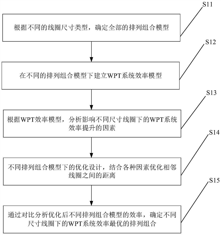
[0062] figure 1 It shows a flow chart of a method for optimizing the multi-relay coil coupling structure of a long-distance WPT system in an embodiment of the present invention, and the optimization method includes:

[0063] S11: Determine all permutation and combination models according to different coil size types.

[0064] Specifically, when the number of coils of various sizes is sufficient, according to the position of the multiple relay coils in the WPT system, the size of the coils, and the number of coils, the transmitting coil, the relay coil and the receiving coil can be determined. There are n kinds of situations for placing coils, and according to the permutation and combination calculation, the WPT system has n n -n kinds of permutation and combination models.

[0065] S12: Establish WPT system efficiency models under different permutation and combination models.

[0066] The compensation capacitance C of the transmitting coil, the relay coil and the receiving ...

Embodiment 2

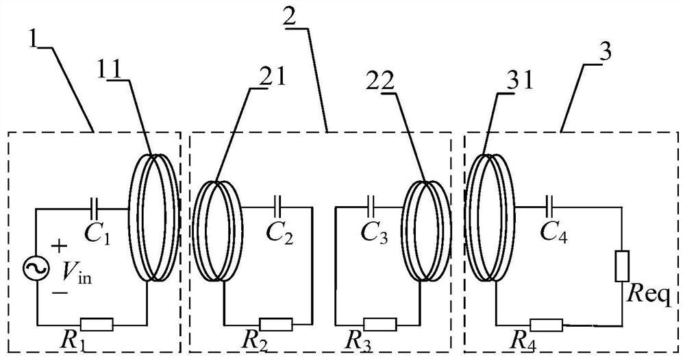
[0111] figure 2 It shows a schematic structural diagram of a long-distance WPT system in an embodiment of the present invention. The WPT system includes a transmitting-side structural unit 1, a relay-side structural unit 2, and a receiving-side structural unit 3. The transmitting-side electrical circuit of the transmitting-side structural unit 1 Including the transmitting coil 11, the voltage of the DC input power supply of the transmitting side structural unit 1 is V in , the relay side electrical loop of the relay side structural unit 2 includes a first relay electrical loop and a second relay electrical loop, the first relay electrical loop includes a first relay coil 21, and the second intermediate electrical loop The relay circuit includes a second relay coil 22 , and the receiving-side electrical circuit of the receiving-side structural unit 3 includes a receiving coil 31 .

[0112] Specifically, the mutual inductance between the transmitting coil 11 and the first rela...


PUM


Abstract

The invention discloses a long-distance WPT system multi-relay coil coupling structure optimization method and device, and the method comprises the steps: determining all permutation and combination models according to different coil size types, building a WPT system efficiency model under different permutation and combination models, and, according to the WPT efficiency model, analyzing factors influencing WPT system efficiency improvement under coils of different sizes and optimization design under different permutation and combination models; and optimizing the distance between adjacent coils in combination with various factors, and determining the permutation and combination with the optimal efficiency of the WPT system under the coils of different sizes by comparing and analyzing the efficiency of different permutation and combination models after optimization. According to the method, the permutation and combination with the optimal efficiency are determined by optimizing the distance between the adjacent coils, so that the system always works in an efficient state in the energy transmission process, and the problem that the efficiency is low in the middle and long distance wireless power transmission process is effectively solved.

Description

technical field [0001] The invention mainly relates to the technical field of wireless charging, in particular to a method and device for optimizing the coupling structure of multiple relay coils in a long-distance WPT system. Background technique [0002] Wireless Power Transfer (WPT) is an emerging technology that can transfer energy from the power source side to the load side without direct contact. Among them, the inductive WPT technology has been widely used because of its safety and reliability. In the field of wireless charging of implantable medical equipment, electric vehicles and mobile devices such as mobile phones. [0003] At present, the long-distance wireless power transmission method is to add a relay side structural unit between the energy transmitting end structural unit and the energy receiving end structural unit, and use the magnetic coupling resonance of the relay coil to realize energy transmission at medium and long distances. The existing multi-repe...

Claims


Application Information

Patent Timeline
IPC IPC(8): G06F30/367G06F30/373H02J50/10H02J50/50G06F111/04
CPCG06F30/367G06F30/373H02J50/10H02J50/50G06F2111/04Y02T10/70Y02T10/7072Y02T90/14
Inventor 吴晓锐肖静尹立群吴宁龚文兰陈绍南韩帅陈卫东卢健斌阮诗雅梁水莹郭敏郭小璇孙乐平赵立夏
Owner GUANGXI POWER GRID ELECTRIC POWER RES INST
Learn More