Squeezing type liquid rocket engine working process simulation device

A liquid rocket and working process technology, applied in the field of aerospace science, can solve problems such as high manufacturing cost, poor visibility, and many complexities, and achieve the effect of improving rationality and integrity, improving intuitiveness, and ensuring safety.

Pending Publication Date: 2022-01-21
NORTHWESTERN POLYTECHNICAL UNIV
View PDF0 Cites 1 Cited by
  • Summary
  • Abstract
  • Description
  • Claims
  • Application Information

AI Technical Summary

Problems solved by technology

But in actual engineering, its workflow and status are difficult to demonstrate and express
And due to the overall unity of the engine and the complexity of the structure, it is difficult to separate a single system, and there are high-temperature and high-pressure parts in the rocket engine work, which also provides a certain degree of difficulty for the demonstration of its workflow
[0003] Squeeze-type liquid rocket engine manufacturing materials have poor visibility, and the work process involves multi-system coordination, high temperature and high pressure and other complex environments. At the same time, the manufacturing cost is too high, so that it does not have the purpose of realizing the demonstration under the premise of maintaining the complete structure of the engine.

Method used


Image

  • Squeezing type liquid rocket engine working process simulation device
  • Squeezing type liquid rocket engine working process simulation device
  • Squeezing type liquid rocket engine working process simulation device

Examples


Embodiment Construction

[0038] The present invention will be described in detail below in conjunction with the accompanying drawings and specific embodiments.

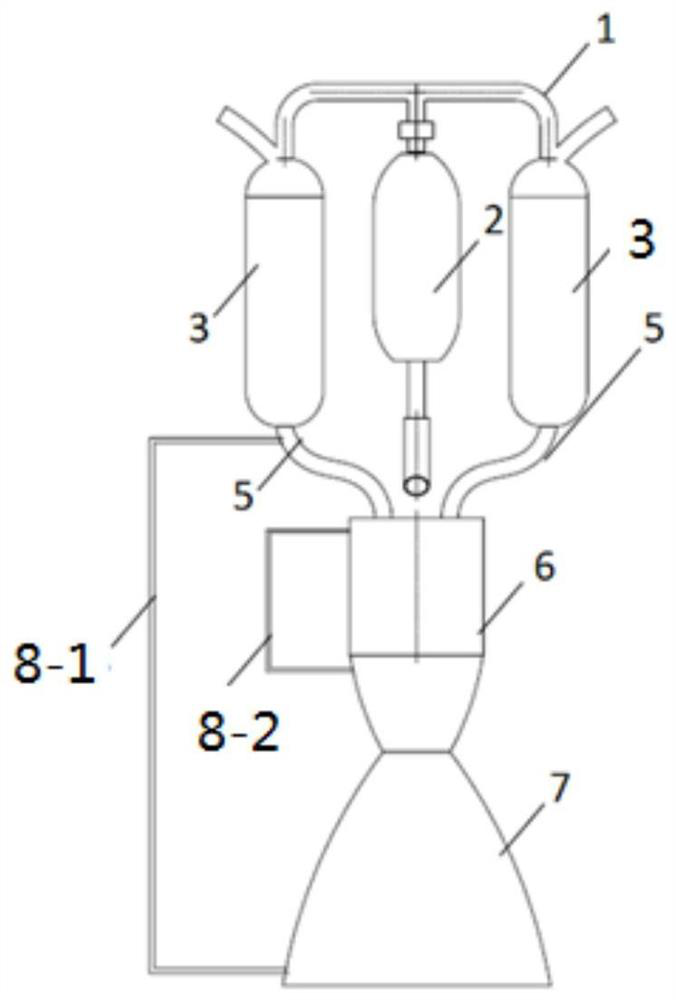
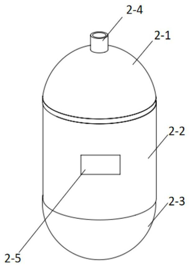
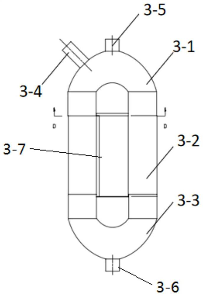
[0039] The invention discloses a device for simulating the working process of a squeeze-type liquid rocket engine, such as figure 1 and 2 As shown, the device includes: a gas storage bottle 2, a propellant storage tank and a combustion chamber 6; the gas storage bottle 2 is a capsule-shaped cavity structure, which is used to set a connected controller and a relay; the gas storage bottle 2 A digital display 2-5 is installed on the side wall, the digital display 2-5 is connected with the relay, and the digital display 2-5 is used to display the change of the analog pressure value. A first connector 2 - 4 is installed at the end of the upper section 2 - 1 of the gas cylinder, and the first connector 2 - 4 communicates with the propellant tank 3 through the delivery pipeline 1 . A power supply circuit is also provided and connected with the con...


PUM


Abstract

The invention discloses a squeezing type liquid rocket engine working process simulation device. The squeezing type liquid rocket engine working process simulation device comprises a gas storage bottle, a propellant storage tank and a combustion chamber, a controller and a relay which are connected with each other are arranged in the gas storage bottle; the side wall of the gas storage bottle is provided with a digital display, the digital display is used for displaying the change of the simulated pressure value, the outer side of each propellant storage tank is provided with a transparent tube along the axial direction, and the transparent tube is filled with liquid; a plurality of liquid level sensors are sequentially arranged in the transparent tube in the length direction of the transparent tube, annular optical fiber lamp strips are arranged around the propellant storage tank and the outer wall of the transparent tube by a circle, the optical fiber lamp strips are arranged in the axial direction of the propellant storage tank at intervals, and in the process that liquid flows into the combustion chamber, the liquid level sensors are used for sensing the position of the liquid in the transparent tube, and is used for displaying the process of pressure reduction of the gas storage bottle and liquid level reduction in the propellant storage tank. According to the simulation device, a single system is stripped from the engine, and the working process of the single system is indicated and expressed.

Description

technical field [0001] The invention belongs to the technical field of space science popularization, and in particular relates to a working process simulation device of an extrusion liquid rocket engine. Background technique [0002] Squeeze supply system is a technology commonly used in liquid rocket engines at present. Squeeze supply system is usually used in small engines such as attitude and orbit control. The propellant content and total impulse of this system are relatively small, and the propellant content of this system , The total stroke is relatively small, the chamber pressure is low, and repeated short pulse work is required. The extrusion system is relatively simple, but it needs high-pressure gas cylinders, storage tanks, etc., so the structural quality of the system is large, and it is generally suitable for small thrust, A propulsion system with lower total flush requirements. The extrusion supply system mainly consists of gas cylinders, pressure reducers, p...

Claims


Application Information

Patent Timeline
IPC IPC(8): G09B25/02F17C1/00F17C13/02
CPCG09B25/02F17C1/00F17C13/025F17C2250/043
Inventor 马驰邓智仁魏祥庚许梦帆赵童朱韶华陈剑陈焱烽
Owner NORTHWESTERN POLYTECHNICAL UNIV
Why Eureka
Try Eureka